With nm cable the wire colors for travelers will be black and red using 3 wire cable. The black wire from the switch connects to the hot on the receptacle.
Toggle Wiring 4 Diagram Switch Pin Illuminated H1 Wiring
Toggle switch wiring diagram. How to wire a on off on toggle switch diagram. The colors will vary depending on whether nm cable or conduit was used. Also included are wiring arrangements for multiple light fixtures controlled by one switch two switches on one box and a split receptacle controlled by two switches. This wiring diagram illustrates adding wiring for a light switch to control an existing wall outlet. A switch loop single pole switches light dimmer and a few choices for wiring a outlet switch combo device. Variety of on off on toggle switch wiring diagram.
The other end of the lamp is connected with neutral line of ac power supply. Collection of 2 pole toggle switch wiring diagram. Below is the schematic diagram of the wiring for connecting a dpdt toggle switch. A wiring diagram is a streamlined conventional pictorial depiction of an electrical circuit. There is no standard for wire colors on 3 way switch travelers. Terminal 2 is connected to power.
1845 x 1742 download. 3 way switch wiring diagram light fixture between switches. On off on toggle switch wiring diagram download. The hot source wire is removed from the receptacle and spliced to the red wire running to the switch. Pin1 of both the switches are connected with the phase or live wire and pin2 of both the switches are connected with the one end of the lamp. A novice s guide to circuit diagrams.
The source is at the outlet and a switch loop is added to a new switch. No longer allowed after 2011 nec if no neutral wire in switch boxes 3 way switch wire colors. Here is a diagram of a spdt toggle switch. As you can see in the schematic diagram of 2 way switch circuit below the common of both the switches are short circuited. In this diagram the incoming hot wire attaches to the first switchs common dark colored terminal. An initial appearance at a circuit layout may be.
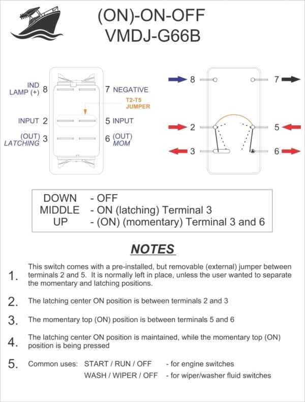
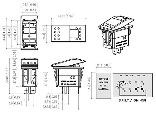
A dpdt toggle switch has 6 terminals. Line voltage enters the first 3 way switch outlet box light fixture is located between switch boxes. This 3 way switch wiring diagram shows how to wire the switches and the light when the power is coming to the light switch. When the electrical source originates at a light fixture and is controlled from a remote location a switch loop is. The two hot wires of three wire cable connect to a pair of brass colored traveler terminals on each switch. Quentacy 19mm 3 4 metal latching pushbutton switch 12v buy quentacy 19mm 3 4 metal latching pushbutton switch 12v power symbol led 1no1nc spdt on off black waterproof toggle switch with wire socket plug blue how to wire a 3 way switch wiring diagram how to wire 3 way light switches with wiring diagrams for different methods of installing the wire between boxes detailed instructions and wiring diagrams.
The switch is always making one of the two connections and flips between them. So if a fan is connected to terminal 1 and a motor is connected to terminal 5 terminal 3. Terminals 3 and 4 represent the toggle switch. These terminals receive the power necessary to drive the loads on terminals 1 and 5 and 2 and 6. We will now go over the wiring diagram of a dpdt toggle switch. Terminal 1 is connected to one load or accessory terminal 3 is connected to another load or accessory.
Click on the image to enlarge and then save it to your computer by. Wiring a switch loop. It shows the elements of the circuit as simplified forms and the power and signal links between the gadgets. This page contains wiring diagrams for household light switches and includes. Terminals 3 can flip between terminals 1 and 5.
Gallery of Toggle Switch Wiring Diagram