Here is a picture gallery about dpdt toggle switch wiring diagram complete with the description of the image please find the image you need. This video is unavailable.

Nt 0590 Use The Form Below To Delete This Dpdt Toggle Switch
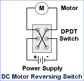
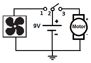
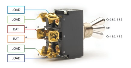
Dpdt toggle switch wiring diagram. Terminal 2 is connected to power. Below is an example of a circuit which utilizes a double pole double throw switch. 2 methods are explained with associated wiring diagrams. You can see above how a double pole double throw switch can allow a circuit to be in 1 of 2 modes. A double pole double throw switch is used for this purpose but you have to wire it up correctly. Sp and dp refer to single pole and double pole st and dt refer to single throw and double throw.
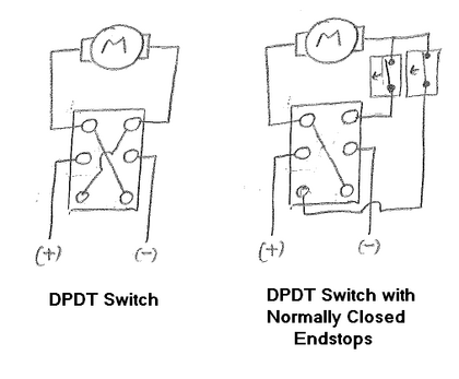
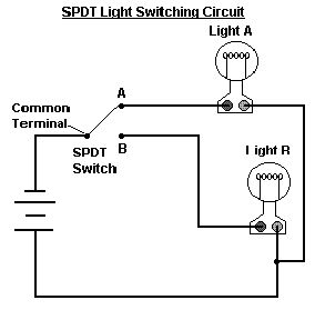
Dp switches control two independent circuits and act like two identical switches that are mechanically linked. In this video i give you the characteristics of a dpdt switch and how to wire. The switch is always making one of the two connections and flips between them. Dpdt toggle switch wiring. Here is a diagram of a spdt toggle switch. It shows the elements of the circuit as streamlined forms and the power as well as signal links in between the gadgets.
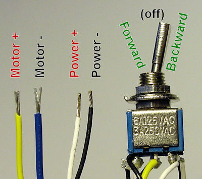
What do spst spdt dpst and dpdt mean. When you need to control a dc motor such as a dc linear actuator you usually need to be able to swap the polarity on the wires going to the motor. This is how you wire a double pole double throw dpdt switch. Skip navigation sign in. Terminals 3 and 4 represent the toggle switch. This is a double pole double throw dpdt momentary illuminated momentary rocker switch it has one ind lamp at the top.
Collection of 6 pin dpdt switch wiring diagram. A wiring diagram generally offers details about the family member position as well as setup of devices as well as terminals on the devices in order to help in building or servicing the gadget. Pole refers to the number of circuits controlled by the switch. When the dpdt switch is switched one way flipped upward in the diagram the lamp and buzzer are both on while the led and speaker are off. How to wire your dpdt switches for your uur kits. A dpdt toggle switch has 6 terminals.
Below is the schematic diagram of the wiring for connecting a dpdt toggle switch. Terminal 1 is connected to one load or accessory terminal 3 is connected to another load or accessory. Sp switches control only one electrical circuit. The wiring diagram to the right will show how to wire and power this 12v 20amp on off on 3 way carling contura rocker switch. A wiring diagram is a streamlined conventional photographic depiction of an electrical circuit. Wire a dpdt rocker switch for reversing polarity.
We will now go over the wiring diagram of a dpdt toggle switch. Toggle switch wiring inside dpdt toggle switch wiring diagram image size 588 x 312 px and to view image details please click the image. How to wire your dpdt switches for your uur kits.
Gallery of Dpdt Toggle Switch Wiring Diagram