On this website we recommend many images about illuminated toggle switch wiring diagram that we have collected from various sites from many image inspiration and of course what we recommend is the most excellent of image for illuminated toggle switch wiring diagram. Basic guitar wiring diagram with 2 humbuckers 3 way toggle switch one volume and one tone control.
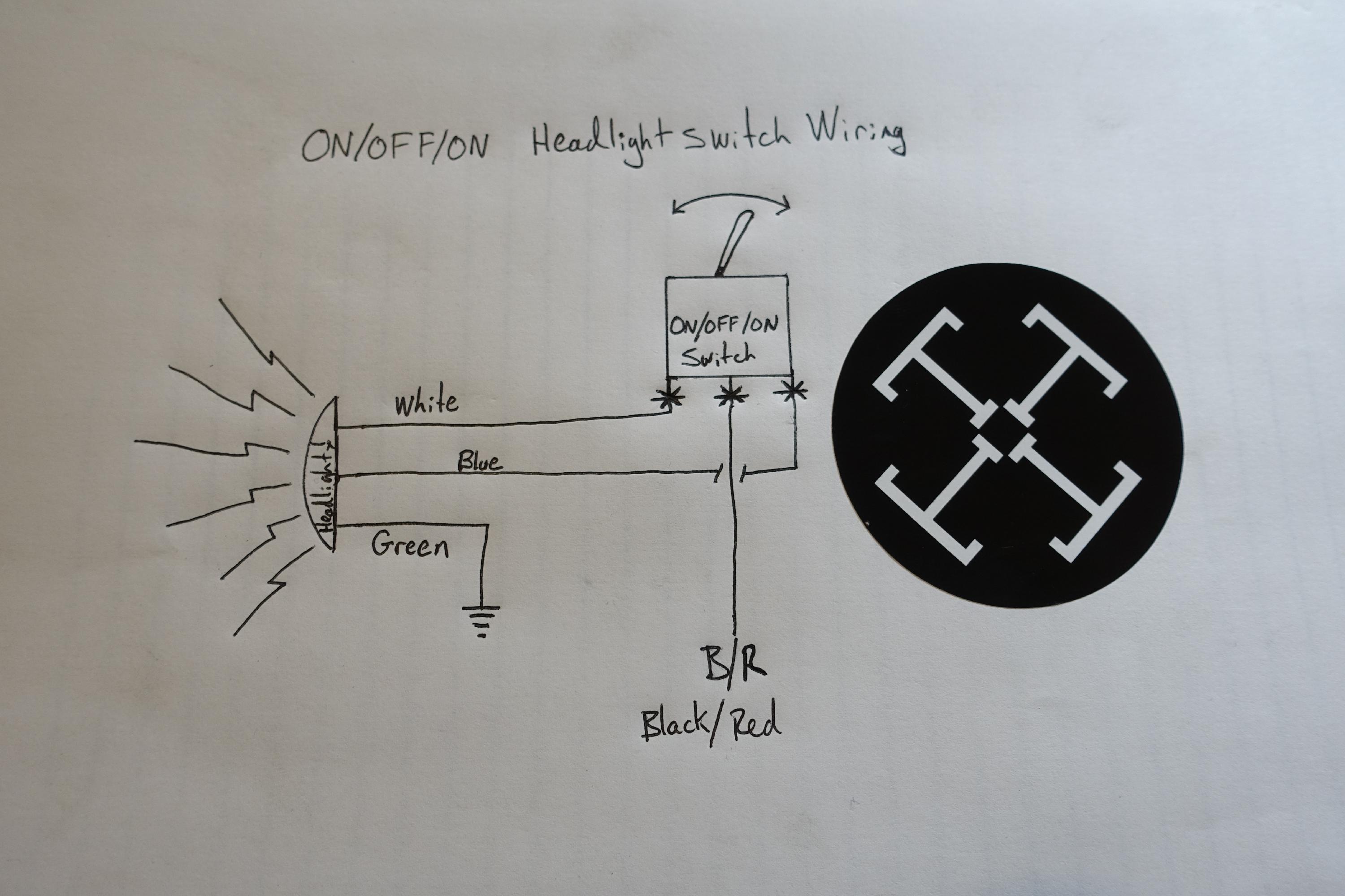
Headlight Switch Wiring For On Off On Toggle Switch Tj
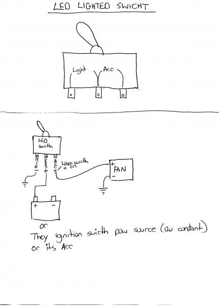
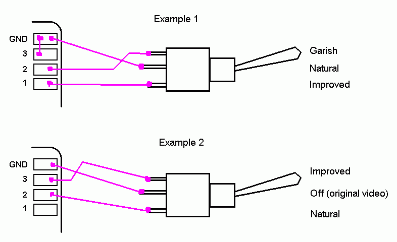
Toggle switch on off on wiring diagram. Terminals 3 can flip between terminals 1 and 5. 8573k2 16 from safran electrical power at allied electronics automation. Terminals 3 and 4 represent the toggle switch. This switch also has a built in led that lights up when its in the on position so if youve purchased one of these below is a wiring diagram showing how you would go about wiring this particular rocker light switch remember to pay careful attention to the markings on the pins. Dont forget the wire solder shielding supplies. Quentacy 19mm 3 4 metal latching pushbutton switch 12v buy quentacy 19mm 3 4 metal latching pushbutton switch 12v power symbol led 1no1nc spdt on off black waterproof toggle switch with wire socket plug blue how to wire a 3 way switch wiring diagram how to wire 3 way light switches with wiring diagrams for different methods of installing the wire between boxes detailed instructions and wiring diagrams.
A dpdt toggle switch has 6 terminals. On off on toggle switch wiring diagram just whats wiring diagram. 3 way or 2 way. Description1universal for all cars motorcycles buses boats marine trailerskitchen appliance etc2rocker switch6 terminals onoffon switch high quality longer life for use3product soldering precautionsany incorrect soldering operation may result the pin in deformation and poor switch contact. How to wire a on off on toggle switch diagram. We will now go over the wiring diagram of a dpdt toggle switch.
How to wire a toggle switch on off switch basic. On off on rocker switch for automotive use with wiring products. Scion oem style rocker switch wiring diagram. On off on toggle switch wiring. Symbols that stand for the components in the circuit as well as lines that represent the links in between them. Wellborn assortment of on off on toggle switch wiring diagram.
So if a fan is connected to terminal 1 and a motor is connected to terminal 5 terminal 3. A wiring diagram is a kind of schematic which makes use of abstract photographic icons to reveal all the affiliations of parts in a system. Be sure to pay attention to the following points when wiringselect the appropriate soldering iron to speed up the soldering. It is recommended to use 20w soldering iron to complete the. On off on toggle switch wiring diagram. Spst toggle switch wiring.
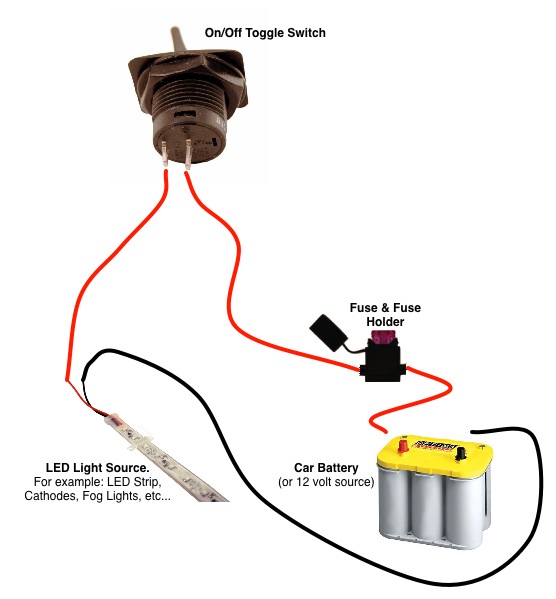
It reveals the components of the circuit as simplified forms and also the power as well as signal links in between the devices. Generally used in 12volt installs for on off switches. Circuitry representations are made up of two points. July 11 2018 by larry a. Wiring diagram images detail. Below is the wiring schematic diagram for connecting a spst.
Dont forget the ready to start. Applies to spot switches non led switches basic 2 wire switches 2 prong. These terminals receive the power necessary to drive the loads on terminals 1 and 5 and 2 and 6. Below is the schematic diagram of the wiring for connecting a dpdt toggle switch. We will now go over the wiring diagram of a spst toggle switch. A wiring diagram is a streamlined standard photographic representation of an electrical circuit.
Gallery of Toggle Switch On Off On Wiring Diagram