If not the arrangement wont work as it should be. Types of single phase induction motors electrical a2z single phase induction motors are traditionally used in residential applications such as ceiling fans air conditioners washing machines and refrigerators single phase motor wiring with contactor diagram the plete guide of single phase motor wiring with circuit breaker and contactor diagram.
2f3e 115 Volt Single Phase Motor Wiring Diagrams Wiring Library
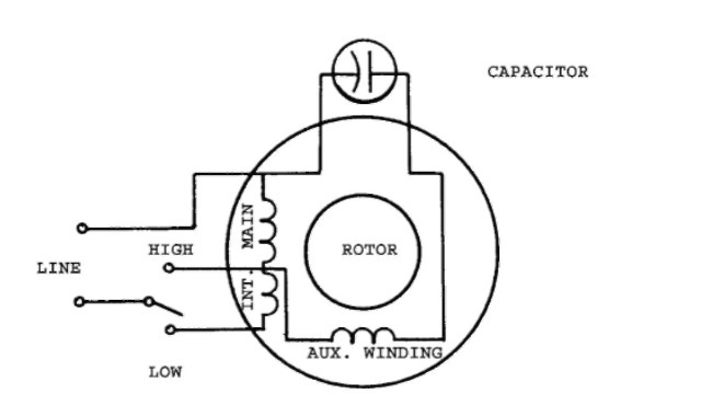
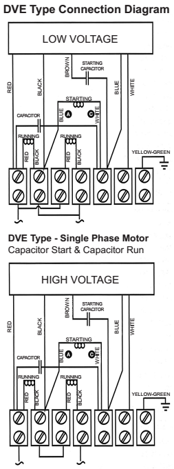
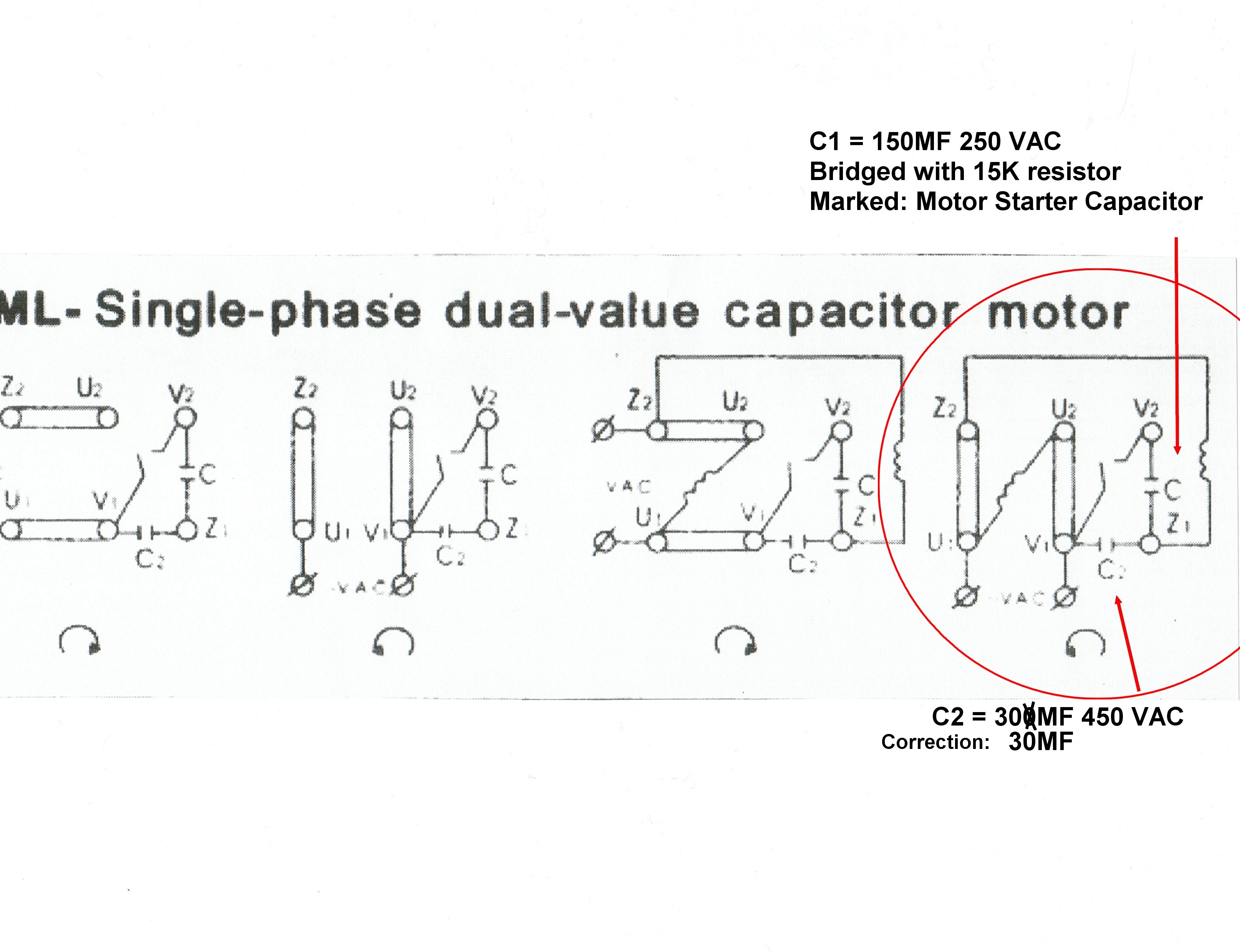
Single phase 2 speed motor wiring diagram. Single phase motor wiring diagram with capacitor start. Split phase single value capacitor electric motor dual voltage type. Diagram dd6 diagram dd7 m 1 ln e diagram dd8 ln e l1 l2 l3 sc z1 u2 z2 u1 cap. Please help how to go about this. It is important to point out from the phasor diagram that the phase difference between im and is is almost 80 degrees as against 30 degrees in a split phase induction motor. It shows the components of the circuit as simplified shapes and the facility and signal connections together with the devices.
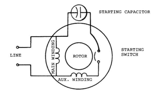
Thus a capacitor start induction run motor produces a better rotating magnetic field than the split phase motors. This is a constant speed motor and is best for light running machines such as fans small blowers business machines grinders etc. Diagram dd5 two speed motors for all other single phase wiring diagrams refer to the manufacturers data on the motor. One contactor burnt for high speed and a replced contactor does not engange originally the coils re fed with a nutural and the one i replaced is only working with a phase. Kindly email me the diagrams for star deltor and direct online for a 3speed 1directon 3ph motor have two of them in a bow cutter. Single phase 2 speed motor wiring diagram wiring diagram is a simplified pleasing pictorial representation of an electrical circuit.
Thermal contacts tb white m 1 z2 yellow z1 blue u2 black u1 red bridge l1 and l2 if speed controller sc is not required m 1 ln e white brown blue l1 l2 n sc bridge l1 and l2 if speed controller sc is not required diagram dd9 1ø wiring diagrams ln e l1 l2 l3 sc z2 u2 z1 u1 cap. Split phase single value capacitor electric motor dual voltage type. Amazon sells motor start capacitors. Single phase motor wiring diagram with capacitor baldor single phase motor wiring diagram with capacitor single phase fan motor wiring diagram with capacitor single phase motor connection diagram with capacitor every electrical arrangement is made up of various unique pieces. Each component ought to be placed and linked to different parts in particular manner. It is to be.
It is evident from the phasor diagram that the current through the starter winding is leads the voltage v by a small angle and the current through the main winding im lags the applied voltage.
Gallery of Single Phase 2 Speed Motor Wiring Diagram