Always photograph switch wiring 2 each 3 speed fan switch has only one wire that connects to hot wire. Neutral and 3 hots.

Bd 3344 Salzer Toggle Switches Wiring Diagram Download Diagram
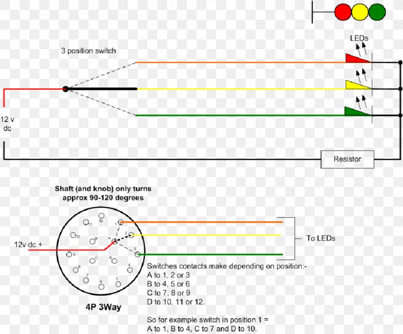
Selector switch wiring diagram. A wiring diagram is a streamlined traditional pictorial representation of an electrical circuit. Here is a picture gallery about 3 position selector switch wiring diagram complete with the description of the image please find the image you need. Variety of 4 position selector switch wiring diagram. Ammeter switches with 0 position start selector switches. 2 position selector switch 3 position selector switch 2 position selector push button no. Power to hot wire.
Need help wiring 3 position selector switch for brewtroller home within 3 position selector switch wiring diagram image size 640 x 480 px and to view image details please click the image. The source is at sw1 and 2 wire cable runs from there to the fixtures. 2 cap leads 1 resistor lead 1 pickup hot wire. Note which wiresjump to index. Double circuit mushroom head wobble. Each wiring diagram is shown with a treble bleed modification a 220kω resistor in parallel with a 470pf cap added to the volume pots.
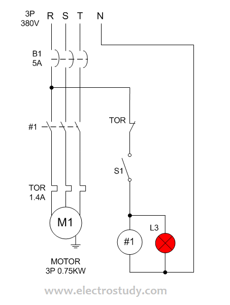
The hot and neutral terminals on each fixture are spliced with a pigtail to the circuit wires which then continue on to the next light. On the other hand this diagram is a simplified version of the structure. Single engine two batteries. It reveals the parts of the circuit as simplified forms and also the power and also signal connections between the tools. Battery switch wiring diagrams single engine single battery diagram. Ammeter selector switch with centre off 3 transformers 1 pole.
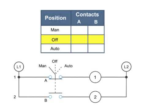
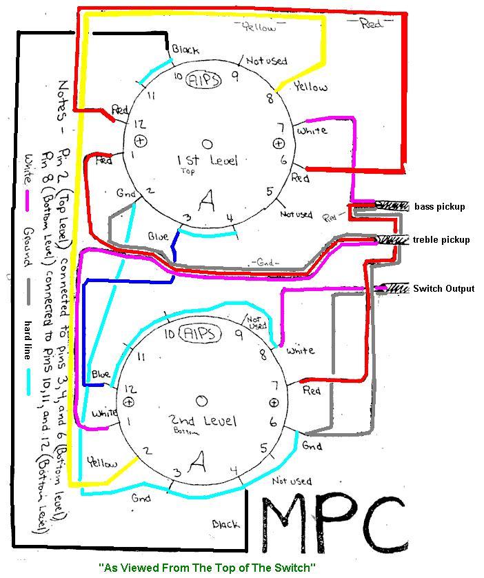
Lets say switch is in off position. This makes the procedure for assembling circuit easier. Common electric guitar wiring diagrams. Speaker selector switch wiring diagram 8 in 7 wiring diagram speaker selector switch wiring diagram the diagram offers visual representation of a electrical arrangement. Es 335 prewired standard assembly. Wiring diagram book a1 15 b1 b2 16 18 b3 a2 b1 b3 15 supply voltage 16 18 l m h 2 levels b2 l1 f u 1 460 v f u 2 l2 l3 gnd h1 h3 h2 h4 f u 3 x1a f u 4 f u 5 x2a r power on optional x1 x2115 v.
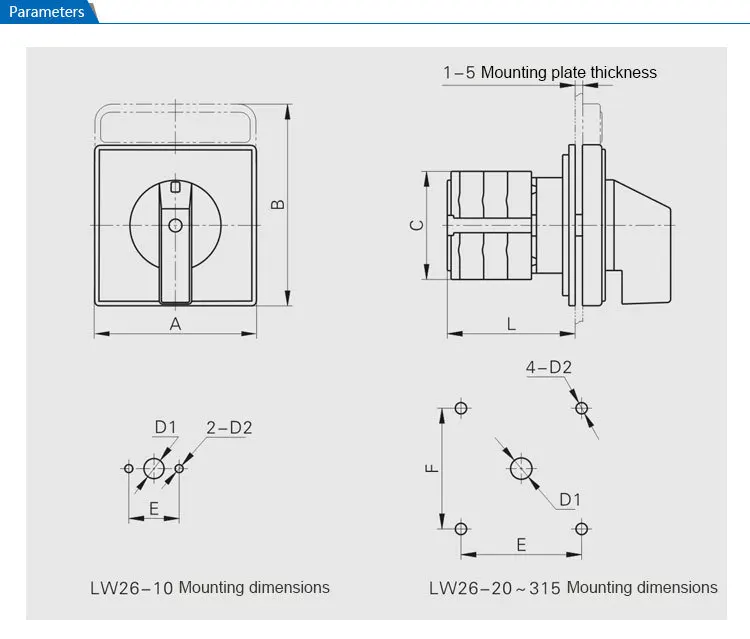
Rotary cam switches from salzer are manually operated independently programmable. A wiring diagram normally offers details regarding the loved one position as well as plan of tools as well as terminals on the gadgets to aid in building or servicing the tool. But adding on off switches to the circuit you can force the alternator to charge the battery you want charged. In basic diagram there are four wires that connect to the motor. There are different types of 3 speedfour wire switches. Salzer switches s tp rt series are.
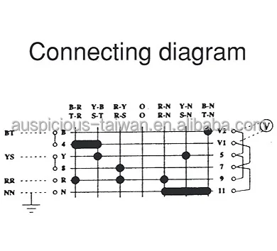
Switching diagrams and further switching programmes page detailed. This diagram illustrates wiring for one switch to control 2 or more lights. Running with a selector switch in the both position see selector switches may not fully charge all batteries.
Gallery of Selector Switch Wiring Diagram