Running with a selector switch in the both position see selector switches may not fully charge all batteries. The idea and the plan.

Nh 7474 Switch Wiring Diagram Rotary Switch Wiring Diagram
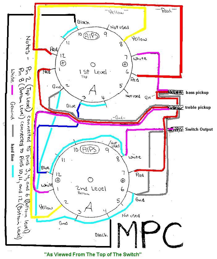
2 position selector switch wiring diagram. Need help wiring 3 position selector switch for brewtroller home within 3 position selector switch wiring diagram image size 640 x 480 px and to view image details please click the image. Illuminated 1 7 2 and 3 position dimensional drawings 1 8 wiring diagrams 1 8 installation instructions 1 8 selector switches. Diagram 1 page 1basic guitar wiring diagram with 2 humbuckers 3 way toggle switch two volumes and one tone control. Wiring diagrams 1 6 installation instructions 1 6 push pull operators. For the 5 positions on the switch i needed these combinations. How to connect 2 way switch wiring using three wire control.
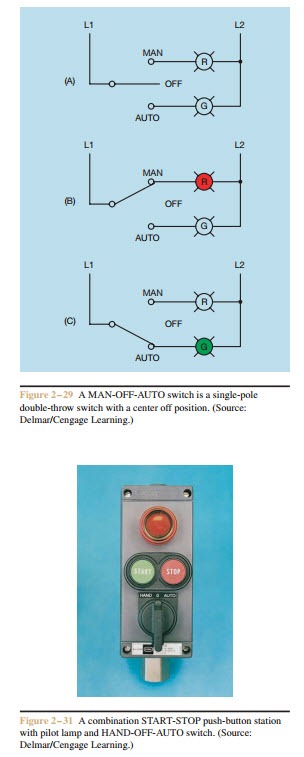
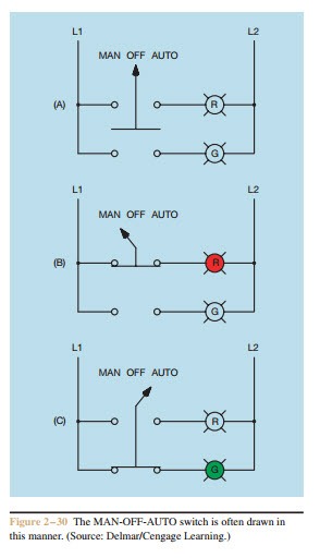
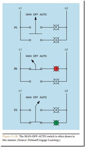
I 2 bo 0 ed a x b x f c r anti plugging heavy duty selector 3 position 1 2 3 s 0 fid swtwt. This is the new method to make a 2 way switching connection as it is slightly different from the two wire control method. Learn how this truth table illustrates the manual or automatic contact positions of two contact selector switch. Double circuit mushroom head wobble. I like things simple so my preference is for a single volume and single tone control both of which i use a lot. 2 position selector switch 3 position selector switch 2 position selector push button no.
2 position 1 9 illuminated non illuminated keyed dimensional drawings 1 10 installation instructions 1 10 selector switches. This method is commonly used now days as it is efficient than the two wire control system. Selector switch jo jo 2 position 3 position heavy duty selector 2 position 1 2 letter posltlon al sm. Here is a picture gallery about 3 position selector switch wiring diagram complete with the description of the image please find the image you need. Outside coils of both humbuckers 3. Wiring diagrams do not show the.
Wiring diagram book a1 15 b1 b2 16 18 b3 a2 b1 b3 15 supply voltage 16 18 l m h 2 levels b2 l1 f u 1 460 v f u 2 l2 l3 gnd h1 h3 h2 h4 f u 3 x1a f u 4 f u 5 x2a r power on optional x1 x2115 v. 2 volume no tone so that in the middle position i can adjust the i have all the pots wiring bus and a solderless 3 way blade selector switch. If you have any questions or doubt about how to use install or wire any battery switch consult a certified marine. Where 0 represents the off condition and 1 represents the on condition. Contact position on a selector switch can easily be illustrated using truth tables. So this is designed for hard wiring my favorite five sounds for now onto a 50way switch.
Volume pot outputs to switch pickup inputs. But adding on off switches to the circuit you can force the alternator to charge the battery you want charged. Lever mounted on the front of the switch.
Gallery of 2 Position Selector Switch Wiring Diagram