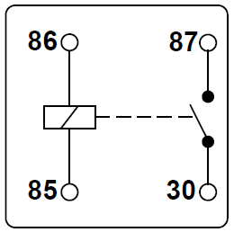
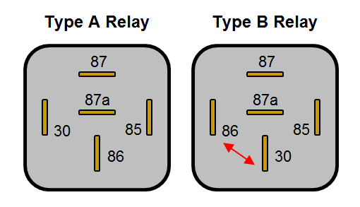
Relay switch pin diagram. 87 and 87a are the two contacts to which 30 will connect.

12v Automotive Diode Automotive
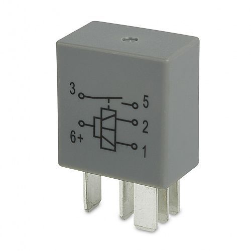
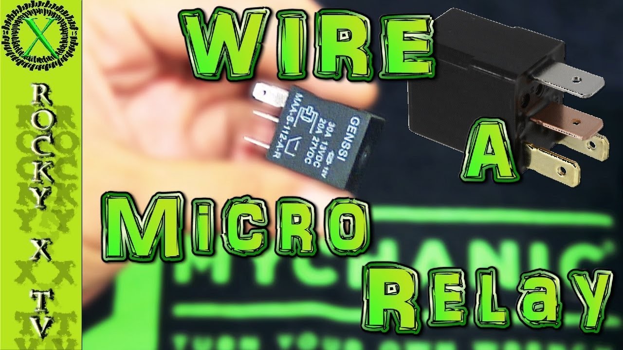
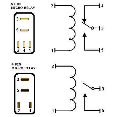
Micro relay wiring diagram. 4 5 1951 first hot wire flasher unit 1960 a relay with metal housing. They are rectangular in section and narrower than a mini relay with a slightly different pin layout and are typically available in make and break and changeover configurations with and without suppression diodes. 75735 rated voltage rated current 10 at 23c ma coil resistance 10 at 23c. A normally open relay will switch power on for a circuit when the coil is activated. It reveals the components of the circuit as simplified shapes and also the power and signal connections in between the tools. Iso micro relays are as the name suggests smaller than iso mini relays and designed for use in applications where space is at a premium.
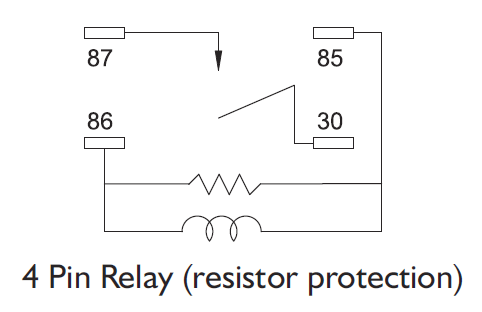
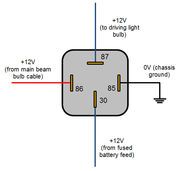
It prevents voltage drop to an accessory which would reduce the efficiency of the accessory and prevent overloading of switches and existing wiring circuits. Current controlled relay for direction indicator lamps bi stable relay for switching between low and high beam. A wiring diagram is a simplified traditional pictorial depiction of an electrical circuit. Applications include electric aerials. 5 pin relay 5 pin relays provide 2 pins 85 86 to control the coil and 3 pins 30 87 87a which switch power between two circuits. They have both normally open and.
Assortment of 12 volt relay wiring diagram. In addition relays are also widely used to switch starting coils heating elements pilot lights and audible. So that we attempted to find some great relay 4 pin wiring diagram graphic for your needs. Numbers of a relay looking at the diagram we see the pinout of a typical 12v relay. The first fully electronic flasher unit 1968 l relay. 85 and 86 are the coil pins while 30 87 and 87a are the contact pins.
Change over relays a change over relay is used to change the path of a power source from one circuit to anoth er. Applications include air horns driving lights etc. Dpdt relay switch pin diagram. It shows the elements of the circuit as streamlined forms and the power as well as signal links in between the gadgets. Honestly we also have been noticed that relay 4 pin wiring diagram is being one of the most popular field right now. Lets look at a relay switch pin diagram to get a better idea.
Note that each pin is numbered. Mini micro relays normally open relays a normally open switching relay is used to remotely connect an accessory to a pwer source. Protective relays can prevent equipment damage by detecting electrical abnormalities including overcurrent undercurrent overloads and reverse currents. Spdt relay switch pin diagram. A wiring diagram is a streamlined conventional photographic depiction of an electrical circuit. Relay wiring regarding relay 4 pin wiring diagram image size 609 x 457 px and to view image details please click the image.
A normally closed relay will switch power off for a circuit when the coil is activated. The first modular system 1969 wipewash interval control unit 1970 k relay. Uncontrolled document updated 5510 wiring diagram for. Mechanical threshold voltage controller for windshield wipers 1965 e relay. Relay switch pin diagram.
Gallery of Micro Relay Wiring Diagram