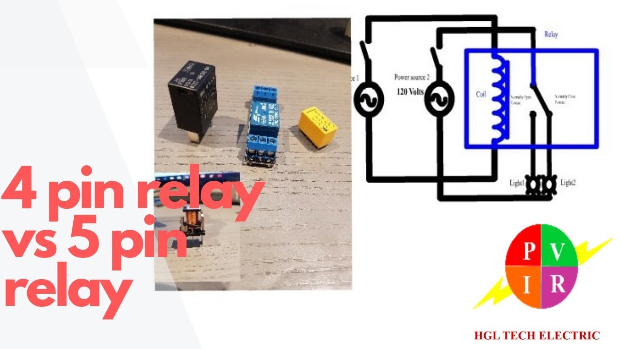
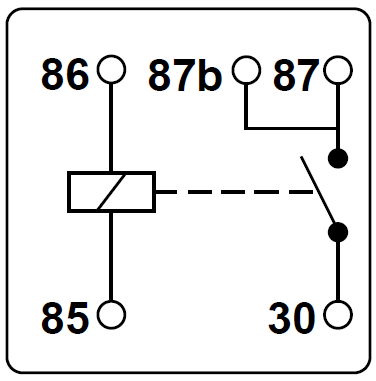
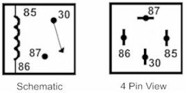
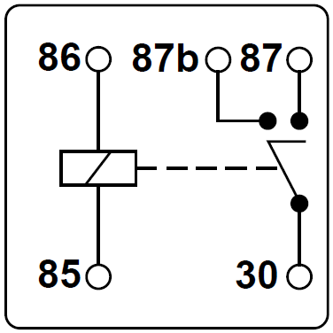
4 pin relay 4 pin relays use 2 pins 85 86 to control the coil and 2 pins 30 87 which switch power on a single circuit. Relay switch pin diagram.
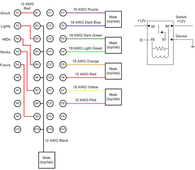
Auxiliary Electrical Infrastructure Mintzer Com
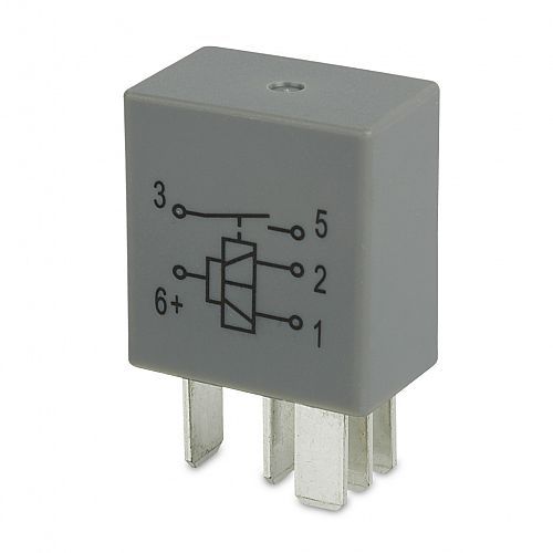
5 pin micro relay wiring diagram. Luis sosa electricidad y electronica. Saved by robert romero. Lets look at a relay switch pin diagram to get a better idea. Normally closed nc not present on 4 pin relays. Plain relay housing no mounting bracket 6615b p1512x 12v 40a diac 1 form a 2 x 87 6621b p1512xwith moulded bracket 12v 40a diac 1 form a 2 x 87 6602b p1524r 24v 30a resistor 1 form a 2 x 87 6616b p1524x 24v 30a diac 1 form a 2 x 87 4 pin normally open mini relays european pin out stock code description type. This video covers both 4 and 5 pin 12vdc relays.
Sep 14 2018 5 pin relay wiring diagram 2 pretty narva 12v relay wiring diagram 5 pin best of in 5 pin relay wiring diagram. The difference between a 4 and 5 pin relay is that a 4 pin relay is used to control a single circuit whereas a 5 pin relay switches power between two circuits. Coil end 1. Electrical projects electrical wiring boat battery battery icon golf cart batteries electric cars electric vehicle wire engine. 5v 5 pin relay module. Best relay wiring diagram 5 pin bosch endearing enchanting blurtsme.
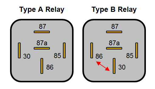
People also love these ideas. Rod hultz automotive electrical projects. Trailer wiring diagram electrical circuit diagram electrical wiring diagram diy electronics electronics projects light switch wiring boat wiring car horn car audio installation. In this video i show you how to wire a 12 volt automotive bosch style relay. There are 2 types of 4 pin relay available. 5 pin normally open mini relays 86 stock code description type protection wiring diagram 6600b p1512r 12v 40a resistor 1 form a 2 x 87 6600ab p1512ro as above.
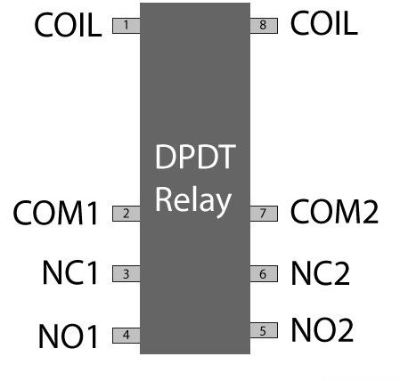
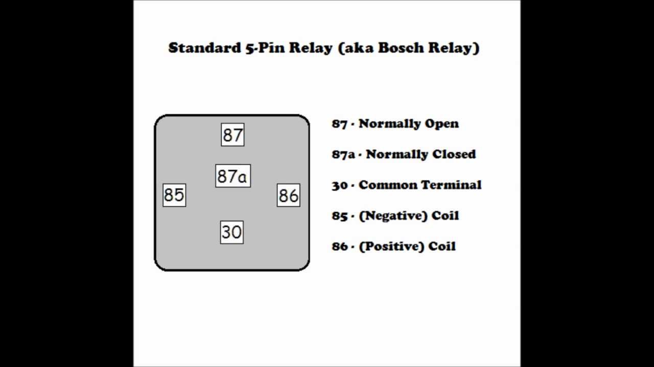
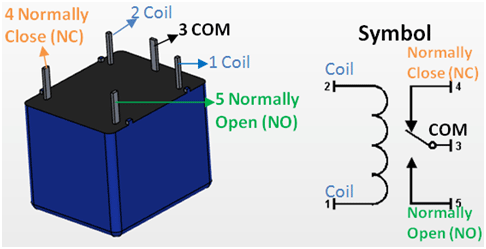
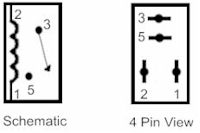
Automotive relays 12v 3040 amp 5 pin spdt designed. The terminals on the outside of a 4 or 5 pin mini relay are marked with numbers as shown below. Click on the image to enlarge and then save it to your computer by right. Electrical symbols electrical diagram electrical projects electrical wiring custom vw bug car door lock go kart plans car audio installation electronics basics. Relay wire diagram 5ab7826eea718 in 12 volt relay wiring diagram. Dpdt relay switch pin diagram.
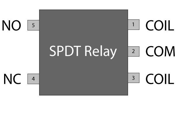
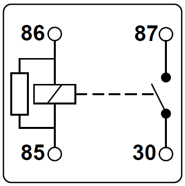
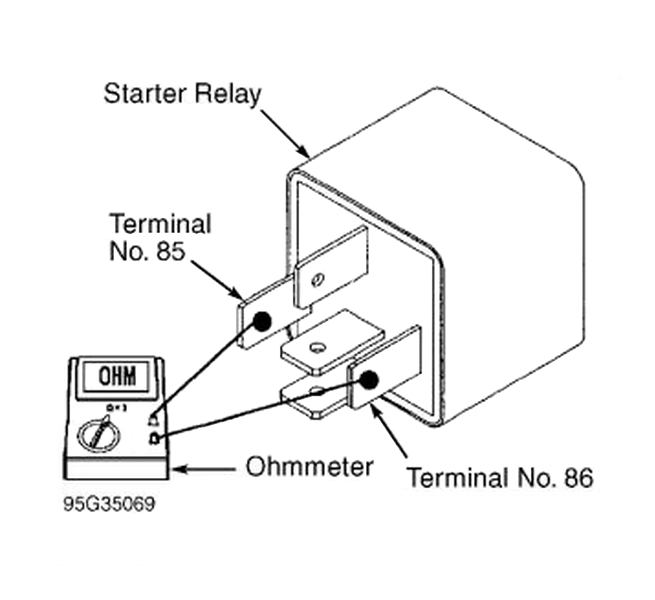
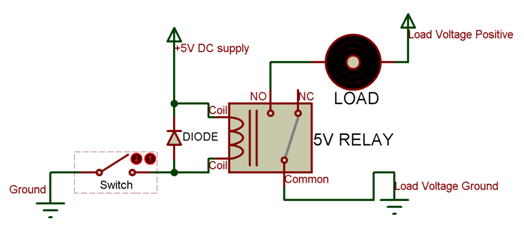
Used to triggeronoff the relay normally one end is connected to 5v and the other end to ground. In addition relays are also widely used to switch starting coils heating elements pilot lights and audible. Relay switch pin diagram. Used to triggeronoff the relay normally one end is connected to 5v and the other end to ground. 5v relay pin diagram click the image to enlarge it relay pin configuration. According to din 72552 the coil should be fed with 12v to terminal 86 and grounded via terminal 85 however in practice it makes no difference which way around they are wired unless you are using a relay with an.
Spdt relay switch pin diagram. Assortment of 12 volt relay wiring diagram. Common com common is connected to one end of the load that is to be controlled. Common connection to no nc terminals. Protective relays can prevent equipment damage by detecting electrical abnormalities including overcurrent undercurrent overloads and reverse currents. 12 volt relay wiring diagram bosch relay wiring diagram 5 pole fresh 5 pin relay wiring diagram inspirational pin relay wiring.
Normally close nc the other end of the. Basic electrical wiring electrical projects electrical symbols car audio installation truck repair car mods diy electronics electric cars custom cars. Normally open no 87a.
Gallery of 5 Pin Micro Relay Wiring Diagram