After the lighting level has been set on one dimmer the other switch will turn the lights off and on at that level. Wiring a ceiling fan dimmer control switch electrical question.

Ceiling Fan Switch Wiring Electrical 101
Hunter 3 speed fan control and light dimmer wiring diagram. 3 way dimmer switch wiring diagrams. Hunter breeze fan light switch. Hunter ceiling fan light switch kit. Wiring diagram for ceiling fan light kit 5 way selector switch 3 at. Amazing ceiling fan with light dimmer switch and. Assortment of hunter 3 speed fan control and light dimmer wiring diagram.
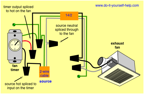
How is a dimmer and fan control switch wired for my ceiling fan. Diagrams for bathroom exhaust fans and timers. Converting an existing ceiling fan to a remote control. 2 black 2 white with ground both white wires are connected together leaving the black wires to be hooked up to the new switch. Ceiling fan light switch replacement dstreetnoshery com. It shows the parts of the circuit as simplified forms and the power and signal links between the gadgets.
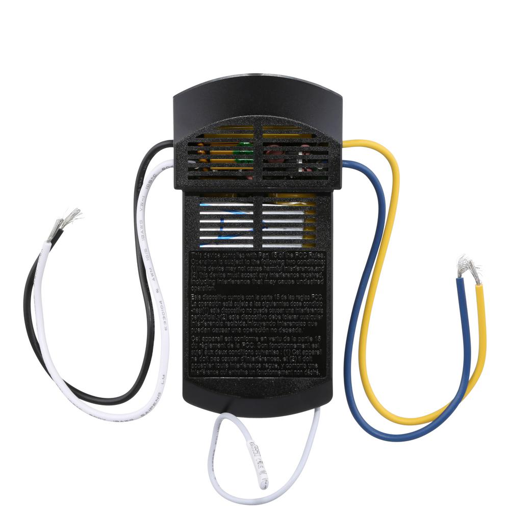
Does anyone have a wiring diagram for recent hunter ceiling fans including the sell the entire switch housing containing the switch capacitor etc. From the switches 3 wire cable runs to the ceiling outlet box. Hunter ceiling fan light kit not working luxury best hampton bay. 0 freescale semiconductor 3 figure 2. A wiring diagram is a streamlined conventional photographic representation of an electrical circuit. Call the lutron hotline 800 523 9466 to ordercall lutron customer service 610 282 3800 neutral black dimmer switchfan speed control hot black or red 120vac 60hz lighting green load or fan or brass screw terminal or green screw terminal ground wire connectors control load side neutral hot yellow green.
The following 3 diagrams show the wiring for a specially made dimmer that can be used in these circuits in place of either of the the 3 way switches or both. Ceiling fans and light kits dimmer switches fan speed controllers 3 way fan switches and bathroom exhaust fan circuits. A wiring diagram is a simplified traditional pictorial representation of an electrical circuit. Psc starting mechanism 22 typical solutions motors commonly used in ceiling fans are single phase induction motors with a psc starting mechanism. Hunter ceiling fan light replacement parts douglas. 4 wires come out of wall.
It shows the parts of the circuit as streamlined forms as well as the power and also signal links between the tools. Wiring diagrams for a ceiling fan and light kit. This arrangement allows for lowering the lights in a 3 way circuit. Collection of hunter 3 speed fan switch wiring diagram. Installing a ceiling. A wiring diagram is a simplified traditional photographic representation of an electric circuit.
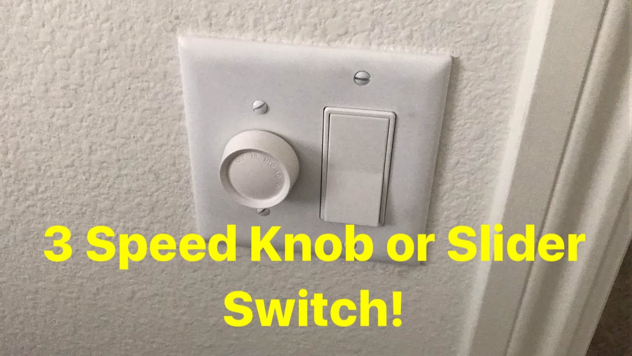
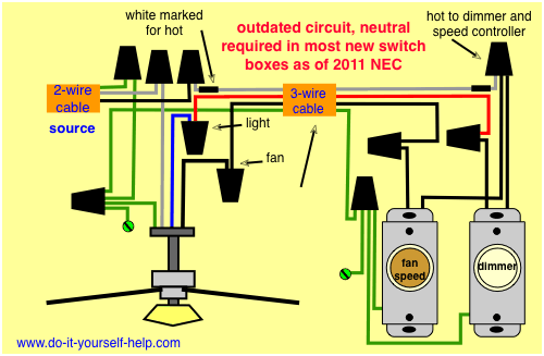
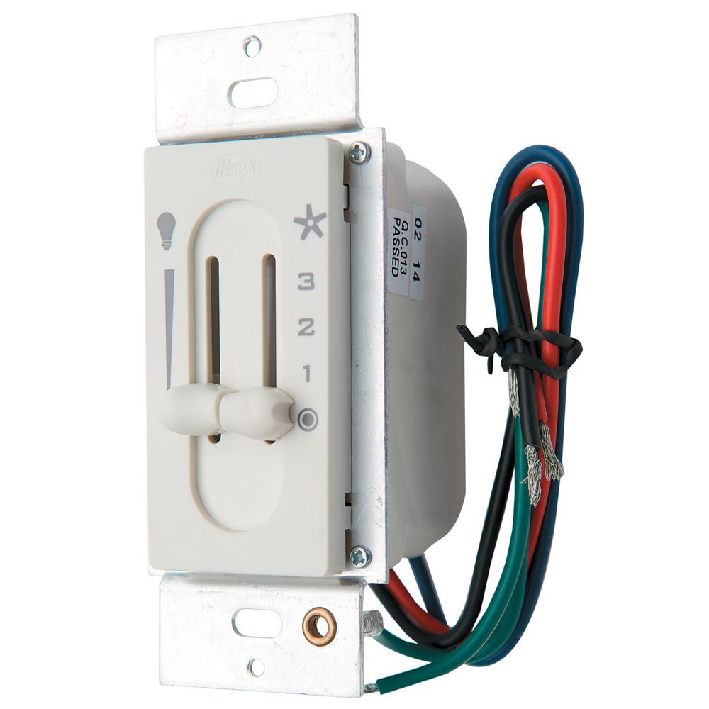
Replacing with hunter model 27182 dimmer fan control switch. This device can be used in place of any of the 3 way switches in these circuits as well as to dim the lights in a. Clear easy to read wiring diagrams for a ceiling fan with light kit including dimmer and speed controller. It reveals the components of the circuit as simplified shapes and also the power and also signal connections in between the devices. Install or replace a ceiling fan. Wiring diagram 2 single pole wiring of 3 way control model dvfsq f dvlv 103p dvlv 603p dv 103p dv 603p wiring diagram 3 single pole wiring model dvelv 300p have questions.
Assortment of hunter 3 speed fan control and light dimmer wiring diagram. The source is at the switches and the input of each is spliced to the black source wire with a wire nut. Ceiling fan light kit wiring diagram as well hunter. This wiring diagram illustrates the connections for a ceiling fan and light with two switches a speed controller for the fan and a dimmer for the lights.
Gallery of Hunter 3 Speed Fan Control And Light Dimmer Wiring Diagram