The first step is to figure out the voltage of your phases. Collection of marathon electric motor wiring diagram.

3 Phase Star Delta Motor Wiring Diagram 3 Phase Motor Earthbondhon
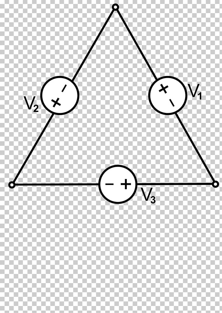
Electric motor wiring diagram 3 phase. Single phase motor wiring diagram with capacitor baldor single phase motor wiring diagram with capacitor single phase fan motor wiring diagram with capacitor single phase motor connection diagram with capacitor every electrical arrangement is made up of various unique pieces. A three pole breaker with an appropriate current rating is used for connecting a three phase motor. A three phase motor must be wired based on the diagram on the faceplate. Three phase motor connection stardelta without timer power control diagrams. Star delta y δ 3 phase motor starting method by automatic star delta starter with timer. Youll also learn.
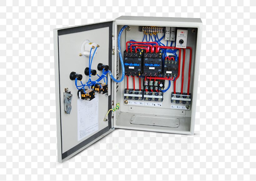
We discuss what a dol starter is its working principle and look at a wiring diagram. 3 phase motor starter wiring diagram sample architectural circuitry diagrams show the approximate locations and affiliations of receptacles illumination and permanent electric solutions in a building. Each component ought to be placed and linked to different parts in particular manner. Wiring diagram book a1 15 b1 b2 16 18 b3 a2 b1 b3 15 supply voltage 16 18 l m h 2 levels b2 l1 f u 1 460 v f u 2. Contactor design and rating contactor nameplate. Ac blower motor wiring diagram furthermore 3 phase star delta motor connection diagram besides dc electrical motor wiring diagram further 813 tube lifier schematic furthermore three phase induction motor rotor and stator.
How to wire a contactor and overload. Click on the image to enlarge and then save it to. Three phase motor power control wiring diagrams three phase motor connection schematic power and control wiring installation diagrams. That being said there is a wide range of different motors and what you have on hand can be completely different. Marathon electric motor wiring diagram single phase marathon motor wiring diagram download single baldor motor wiring marathon electric motor wiring. But before we will disuse.
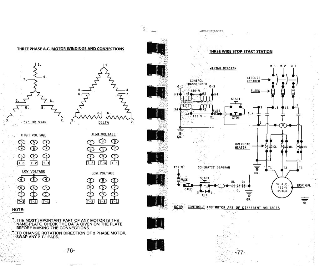
The wiring diagram for connecting thee phase motor to the supply along with control wiring is shown in figure below. A simple explanation of a dol starter direct on line starter. Both 9 wire and 12 wire motors can be connected for high or low voltage operation. A 9 wire motor can only be connected in a wye configuration whereas a 12 wire motor can be connected in either a wye or delta configuration. If not the arrangement wont work as it should be. L1 to t1 l2 to t2 l3 to t3 t4 to t7 t5 to t8 and t6 to t9.
The other 9 wires would be connected as in a 9 wire motor note in a 9 wire motor the equivalent of t10 t11 and t12 are internally connected together. Proper care should be taken while connecting three phase wires to the motor because the direction of rotation can be reversed simply by reversing any of the two wires of three phase system. This is a start stop push button control schematic which includes contactor m overload. In the united states for low voltage motors below 600v you can expect either 230v or 460v. Interconnecting cord routes could be revealed about where particular receptacles or components have to get on an usual circuit. Motor starter schematic and wiring diagram.
Capacitor motor single phase wiring diagrams always use wiring diagram supplied on motor nameplate.
Gallery of Electric Motor Wiring Diagram 3 Phase