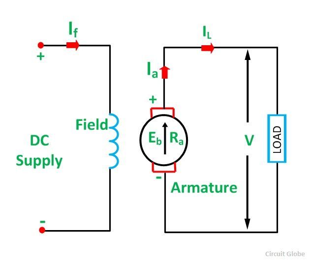
Leviton decora 3 way switch wiring diagram 5603. The basic mechanism of a dc motor.

Typical Wiring For The Pro Dno Vtx And Ncc Controllers
Dc motor wiring diagram 2 wire. Usually the electrical wiring diagram of any hvac equipment can be acquired from the manufacturer of this equipment who provides the electrical wiring diagram in the users manual see fig1 or. Brushless dc electric motor diagram. How to wire a baldor 3 phase motor. It does not rotate when dc powered. 2005 dodge durango wire and fuse diagram. How to wire a motor starter a motor starter is a combination of devices to allow an induction motor to start run and stop according to commands by an operator or a controller typically an induction motor will run by a voltage of 230 volt or 460 volt 3 phase 60 hz in usa and be controlled by a control voltage of 115 volt ac or 24 volt dc motor wiring diagram per nema mg1 1998 176 a wye start delta run motor is one arranged for starting by connecting to the supply with the.
Rotating part with permanent magnet ring with 2 n and 2 s poles. Er 1 2 4 5 ocf. Now for the purposes. Home ac wire diagram. Er 6 oedm. Compact axial fans b 3 single phase motors diag.
How to wire a 3 phase motor and vfd duration. Er 1 2 4 5 ocdevgl gl gamma series d 4345 diags. I prefer dc power. And if this is ac motor may be some simple alternating using h bridge l298. All inductive loads like motors electromagnets and solenoids work on this same principle. Use figure 2 if your motor has a dual voltage shunt field.
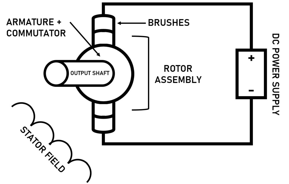
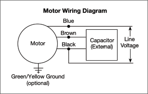
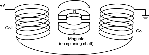
1972 bronco alternator wiring diagram. As the magnets are alternately attracted to one coil and repulsed by the other it spins from one to the other and you get circular motion. Motor connections your motor will be internally connected according to one of the diagrams shown below. It reveals the elements of the circuit as streamlined forms as well as the power and signal connections in between the gadgets. Figure 1 figure 2 single voltage shunt field space heater shunt field arm interpoles series field space heater arm interpoles series field 12. The motor will supply the same amount of power but with a different load.
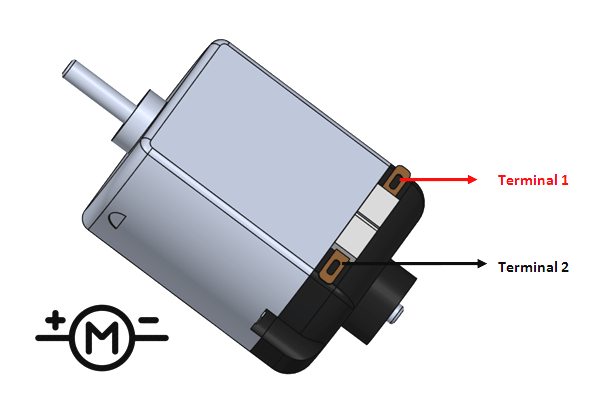
If the single pole switch is toggle closed the motor starter will start and stay on for as long as the single pole switch is closed. Er 1 2 4 5 d 5759 ocdes gamma supply series d 3637 diags. Motor has 2 wires and 4 coils connected in series. A three wire three phase circuit is usually more. In reading further it said not to connect the c wire which happens to be the blue and i also learned this is the common. Use figure 1 if your motor has a single voltage shunt field.
Pgs ocdedv gamma series d 1417 diags. Stratton 12hp startet nicht. These connections are in accordance with nema mg 1 and american standards publication 06. As opposed to dc or direct current ac is the kind of electrical power supplied to homes and other buildings while dc power is primarily used as electrical energy. Motor wiring diagram dc. I believe i need to wire u1 v1 w1 to power and leave u2 v2 w2 disconnected.
2 wire dc proximity sensor wiring diagram download collection of 2 wire dc proximity sensor wiring diagram. If you mount magnets on a spinning shaft surrounded by the wire you have a motor in the diagram below the wire is arranged in two coils. Below is the motor data plate and whats left of the wiring diagram. I want to make it rotating somehow without much requirements in torque and speed. The two wire circuit in configuration 2 operates as follows. Figure 2 illustrates the basic mechanism of a dc motor.
3 phase motor wiring diagram 6 wire. I am trying to wire up a two speed 6 wire 3 phase motor to run at its highest speed. Pyle hydra amplifier wiring. Induce a magnetic. These diagrams are current at the time of publication check the wiring diagram supplied with the motor. A wiring diagram is a streamlined standard photographic depiction of an electric circuit.
These diagrams mainly apply to external rotor motorsbut some standard frame induction motor diagrams have been included for ease of presentation. Century battery charger 87106c wiring diagram. 1978 john deere gator electrical diagram.
Gallery of Dc Motor Wiring Diagram 2 Wire