I am connecting the positive from the battery to the b terminal horns connected to the h terminal horns are grounded on the other end. 12 volt horn wiring diagram see more about 12 volt horn wiring diagram 12 volt horn relay wiring diagram 12 volt horn wiring diagram.
3 Pin Horn Relay Diagram H1 Wiring Diagram
3 pin horn relay wiring diagram. Finding continuity between the horn wire and the vehicle ground requires wiring the relay differently. 12 volt relay wiring diagram. Always check your vehicles owner manual to determine the voltage supply to. Headlight relay wiring diagram the above circuit is a way to use existing headlight wiring to control 2 relays that can be placed close to the lights. It reveals the. Vxk7801 4 pin horn relay with plug.
Best bosch relay wiring diagram 5 pole electrical outlet symbol 2018. This caused the headlights not to work properly. A wiring diagram is a simplified traditional pictorial depiction of an electrical circuit. Its fully insulated and contains up to 7. If you like my video then please subscribe to get the latest updates regarding all. Multimeter used in video.
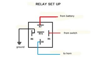
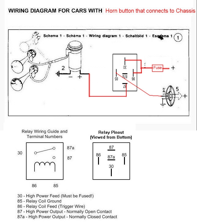
Connect a solderless ring terminal to one wire from the inline fuse holder and connect it to the positive terminal. The switch only controls the relay. Multi purpose relay horn relay. They permit a small circuit to direct a innovative flow circuit using an electromagnet to rule the flow of electricity inside the circuit. Relay wiring diagram 87a visit the post for more 87a relay wiring diagram awesome 4 pin relay wiring diagram. By what the relay box specifies i need to add the s terminal from the relay to ground via a switch not the stock switch provided on the bike.
12 volt wiring diagram best 12v relay pin 5 and roc grp org in. So when the switch is turned on the horn sounds. All listings for this product. This works as intended but i want to use stock horn button to activate the horns. I have with me a 3 pin relayh b s with me. 12 volt horn wiring diagram.
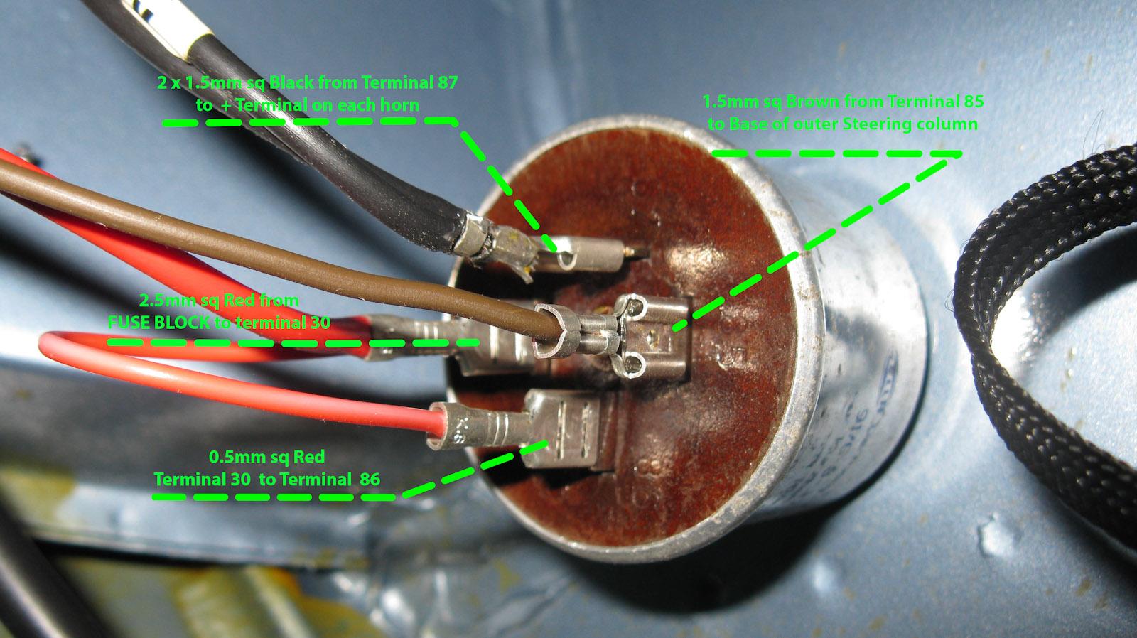
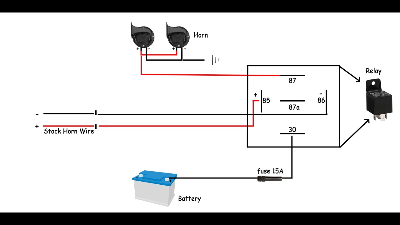
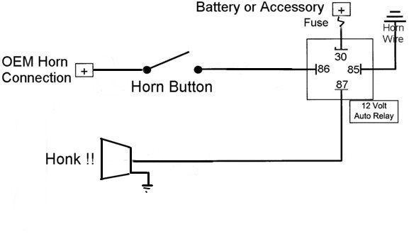
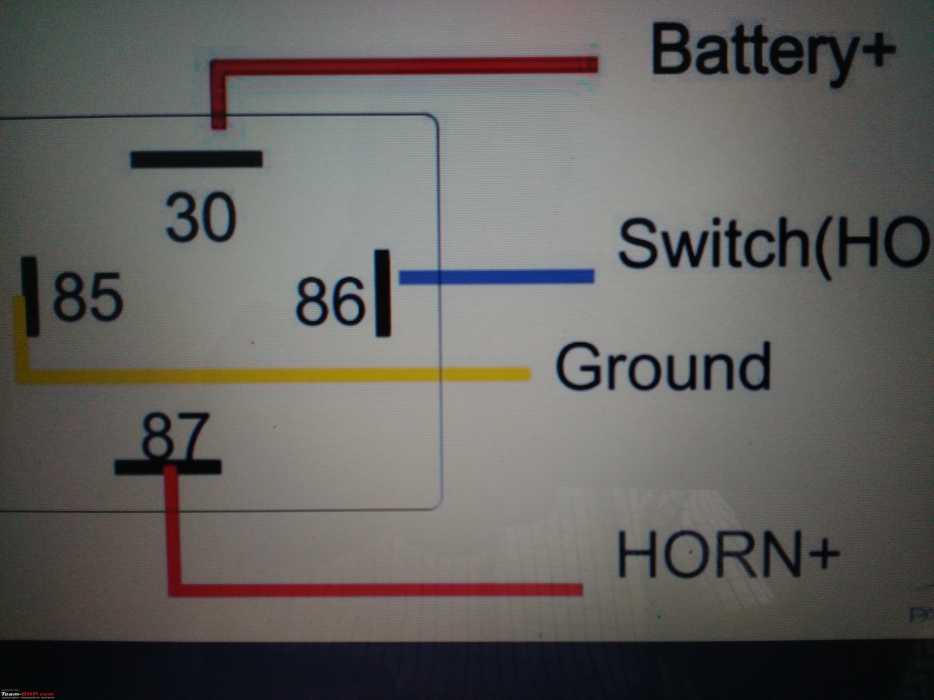
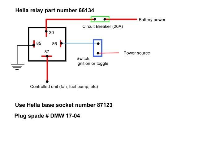
Using a 30 amp spdt relay connect terminal 87 to constant 12 volts positive with a fuse rated to the sum of the additional accessories youve added and the components you need to turn on. They are usually labeled and identified on the mingle box panel. Connect the horn wire to terminal 86 and terminal 85 to terminal 30. This video will help you to connect your horn set with 3 pin relay battery and push push button in your car. Package height 32 in description horn relay feature provides the performance and dependability you expect from acdelco package length 34 in feature manufactured to meet expectations for fit form and function package weight 02 lbs package width 34 in feature professional premium aftermarket replacement. I cover 34 and 5 pin relays and all you need is a 12v source a multimeter and a test light.
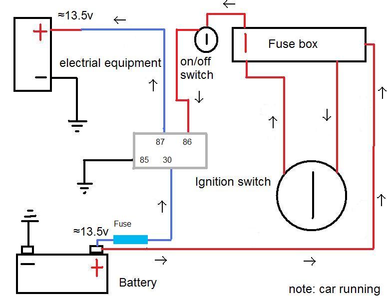
The stock came with a single horn. So use the right size wire. The main power from the battery feeding the fuse and relays should be a nice large gauge wire as indicated. Here is a video on how you can test a relay with or without a diagram. Choose a location close to the battery to reduce the cost of the project by minimizing the amount of heavy gauge wire used. Mount the new horn and relay in a convenient location under the hood.
If you buy 7x6 inch led headlights or 4x6 headlight and your car socket is not standard h4 to 3 pin adapter is a must. Show more show less. September 3 2018 march 13 2019 by larry a. Wiring diagram for a 4 pin relay wiring diagram is a simplified agreeable pictorial representation of an electrical circuitit shows the components of the circuit as simplified shapes and the capacity and signal connections with the devices. Assortment of 12 volt relay wiring diagram. Free wiring diagram menu.
Hvac fan relay wiring diagram download.
Gallery of 3 Pin Horn Relay Wiring Diagram