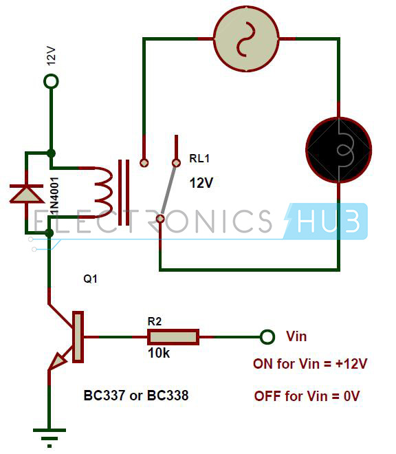
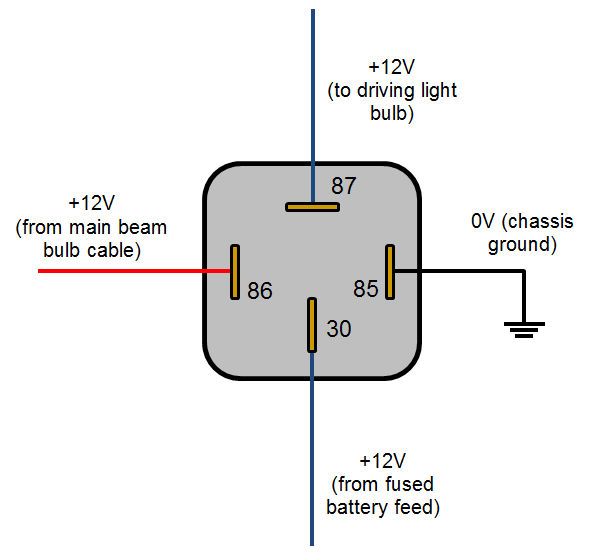
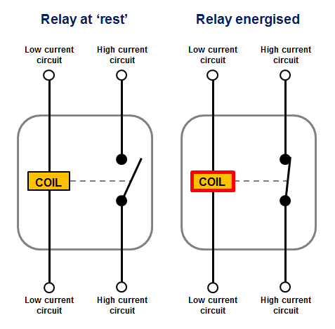
When current starts flowing through the control coil the electromagnet starts energizing and thus intensifies the magnetic field. As shown the power source is given to the electromagnet through a control switch and through contacts to the load.
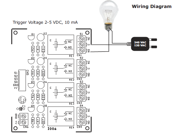
Voltage Levels Control Relays Circuit Diagram
Circuit diagram of relay. We will examine the relay types in more detail below. We discuss what a dol starter is its working principle and look at a wiring diagram. Steering wheel radio control. The transistor allows the hc11 to control the medium sized coil current of relay. Relay circuits electromechanical relays may be connected together to perform logic and control functions acting as logic elements much like digital gates and or etc. Blower motor hi speed relay module.
Electronic relay switch circuit diagram and its working. The relays can be varied as magnetic relays tongue contacts thermal relays overcurrent protection relays. These output devices are commonly called actuators. The diagram shows an inner section diagram of a relay. Youll also learn. Relay switch circuit diagram working of the basic 5v relay circuit.
Drl control module headlamp and instrument panel dimmer switch. An iron core is surrounded by a control coil. The relay type must be selected according to the circuit used. When the switch is closed current start flowing through the coil and by the concept of electromagnetic induction magnetic field is. Connect the relay with hc11 port pins this is used to control on switches. A very common form of schematic diagram showing the interconnection of relays to perform these functions is called a ladder diagram.
There are a variety of electrical and electronic devices which are classified as output devices such devices are used to control or operate some external physical process of a machine or device. Draw the schematic diagram for the relay circuit to be analyzed. Analyze the circuit determining all logic states for given input conditions. Check the accuracy of the circuits construction following each wire to each connection point and verifying these elements one by one on the diagram. In the above circuit 5v relay is powered by a 9v battery. Carefully build this circuit on a breadboard or other convenient medium.
6 way power seats and rear side door actuator motor. Carefully measure those logic states to verify the accuracy of your analysis. August 22 2017 in. If there are any errors carefully check your. A simple explanation of a dol starter direct on line starter. For example overcurrent protection relays can be used to tie the tongue contact if the switch is to be switched on by the magnetic effect and to limit the high current.
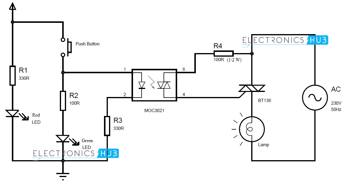
A relay is basically a binary actuator with two stable states. An onoff switch is added for the switching purpose of the relay. High voltage circuit diagrams inverters ups circuit diagrams over voltage protector power supplies relays circuit voltage regulators circuit diagrams no comments when an appliance ceases to k operate there may be various causes for this one of which is the blowing of the mains fuse. Oldsmobile silhouette fuse box instrument panel. The instrument panel fuse block is located to the right of the glove box. At the initial condition when switch is open no current flow through coil hence common port of relay is connected to no normally open pin so the lamp remain off.
Basic schematic circuit diagram of relay the following schematic shows the basic circuit. These actuators convert the electrical energy into physical unit called force speed etc. In this article we will be discussing. Instrument panel fuse block.
Gallery of Circuit Diagram Of Relay