In the 14 pin relay we have 14 pin or connection terminals in which the 4 terminals is. Relays are generally used to switch smaller currents in a control circuit and do not.

14 Pin Relay Base Wiring Diagram H1 Wiring Diagram
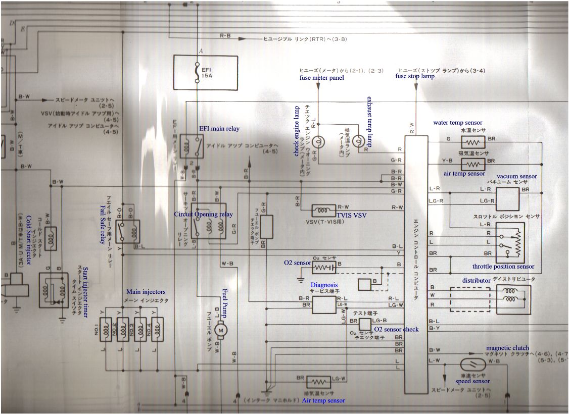
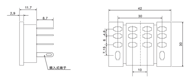
14 pin relay wiring diagram pdf. Relay 8 pin wiring diagram datasheet cross reference circuit and application notes in pdf format. The square relay pinout shows how the relay socket is configured for wiring. Contactors dil 5 14 overload relays z 5 20 zeb electronic overload relay 5 23 zev electronic motor protective system 5 26 thermistor overload relay for machine protection emt6 5 33 cmd contactor monitoring device 5 36. These miniature plug in relays have a 10 ampere resistive rating except for rsrsd41 the same as the type k plug in relays but are much smaller. This pinout image is only a 2 pole diagram for room on the page purposes but you can get the picture here with this one since a 3 pole will just have 1 more set of contacts. Lndicates the reference page showing the position on the vehicle of the parts in the system circuit.
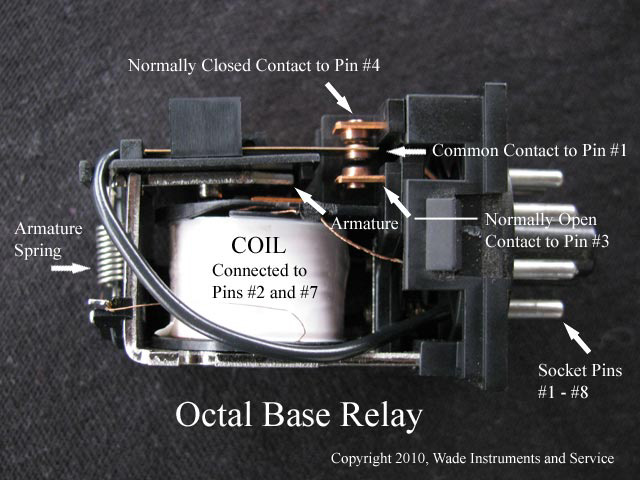
In either case applying electrical current to the contacts will change their state. 4pdt 6 a and 3 a 11 279 11 279 083 210 154 391 027 70 002 05 14 355 024 60 083 210 024 60 full feature cover dimension clear cover dimension dimensions inches millimeters wiring diagrams 11 13 a1 5 9 14 12 1 21 a2 14 6. Pins 8 6 as normally open pins 8 5 as normally closed. They are used in large quantities for the indirect control of motors valves clutches and heating equipment. Spdt through 4pdt ac or dc operated horsepower rated h rs41 and rsd41 relays have a b300 rating. Explains the system outline.
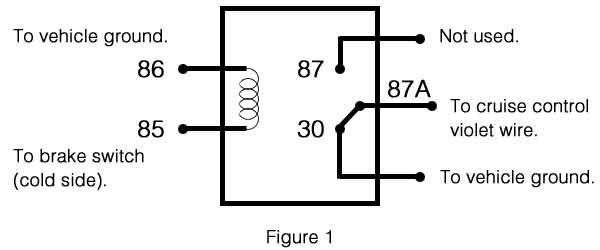
The compact size of these relays makes them ideal for downsizing equipment. In controlling relays 14 pin relay is numbering in those electromagnetic relays which we use in many circuit. Relays switches are used to open and close circuits electromechanically or electronically. Ladder and wiring diagram using an 8 pin electrical relay to turn on and off lights. These relay are connected in a socket which is also called base. Assortment of 12 volt relay wiring diagram.
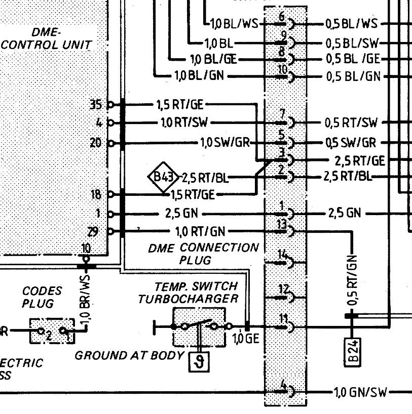
Eaton wiring manual 0611 5 2 contactors and relays 5 5 contactor relays contactor relays contactor relays are often used in control and regulating functions. The letter in the code is from the first letter of the part and the number indicates its order in parts starting with that letter. Indicates values or explains the function for reference during troubleshooting. Otherwise they work exactly the same. When a relay contact is closed there is a closed contact when the relay is not energized. With 14 pin relay we use the base or relay socket in which the relay is inserted.
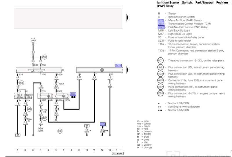
Click on the image to enlarge and then save it to your computer by right. In this post i am sharing a the 14 pin relay base wiring diagram. 8 pin relay wiring. When a relay contact is open the relay is not energized. Part p4 power window master sw is on page 21 of the manual. Enginer control wiring diagram 15 pdf drive search and download pdf files for free.
Here we look at relay switch pin diagram and the different kinds of relay switches. Wiring diagrams magnecraft general purpose relays 792 control series dpdt 12 a. As you can see there is absolutely no difference between the square type and the round type other than the ratings on the relay. 12 volt relay wiring diagram bosch relay wiring diagram 5 pole fresh 5 pin relay wiring diagram inspirational pin relay wiring. 8 pin relay wiring diagram. Enginer control wiring diagram enginer control wiring diagram engine control relay passat wiring diagram engine control relay passat wiring diagram is available in our book collection an online access to it is set as public so you can download it instantly our book servers hosts in multiple locations allowing you to get the most less latency time to download any of our books like this one sxe10 altezza 3s.
Gallery of 14 Pin Relay Wiring Diagram Pdf