The carrierbryantpayne part is hd42ar225. Step 1 smaller industrial motors than these are usually single phase 220 volt.
Switching A Motor Between 240 And 120 Volts
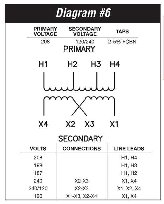
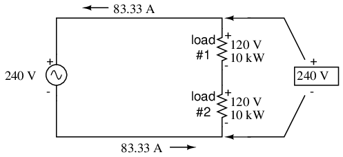
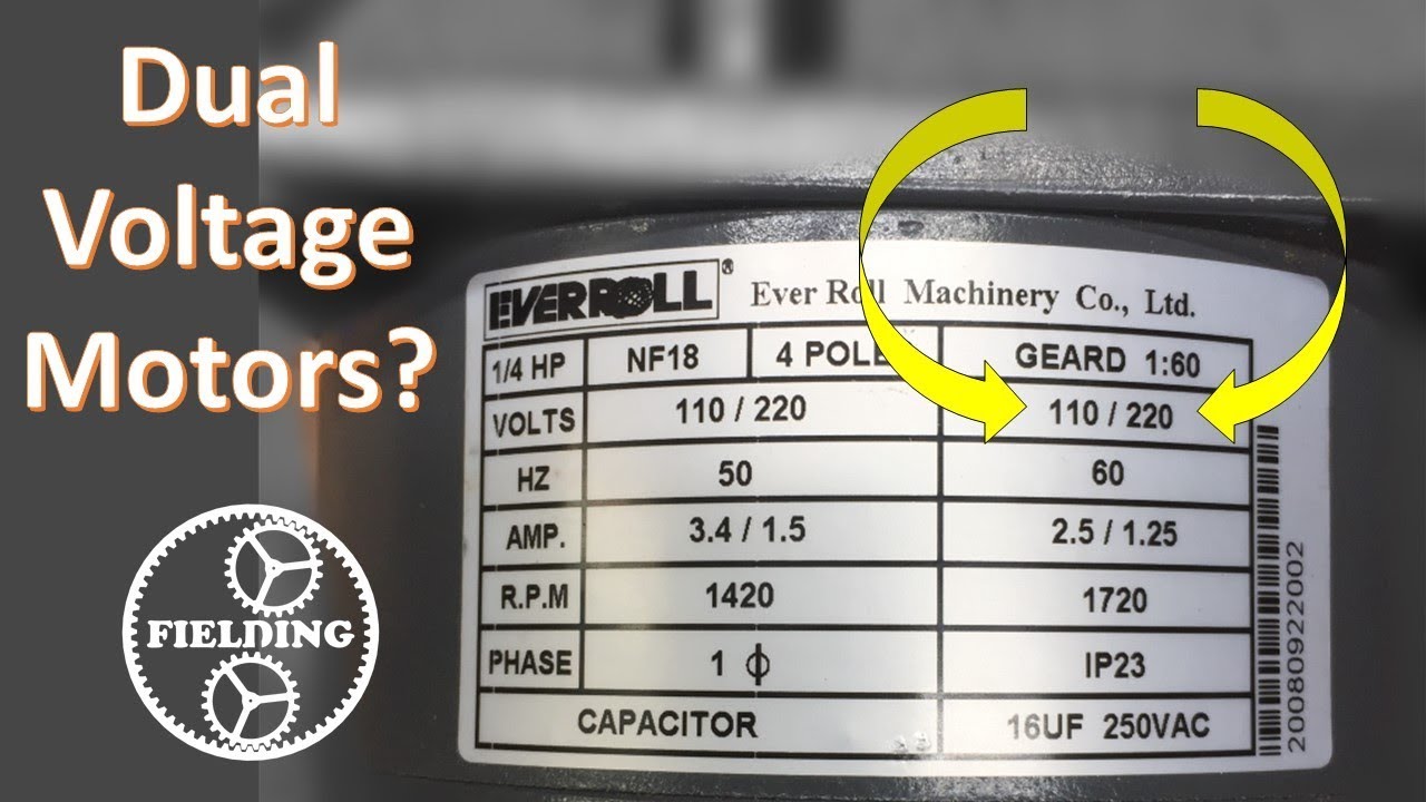
120 240 volt motor wiring diagram. Its 13 hp 120240 volt. This motor running at 120v will have twice the amount of line drop amps x resistance of the wire volts because it is drawing twice the current and it will experience four times the line loss power in watts because amps2 x resistance of the wire watts. The wiring diagram will show that two of the motor wires are connected together for 240 volt wiring. 20 years ago i wired it to 240 volts but i wanted to switch it back to 120 volts. Single phase electric motor wiring tutorial. Wiring a 120240 volt motor for 240 volts is as follows.
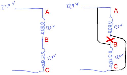
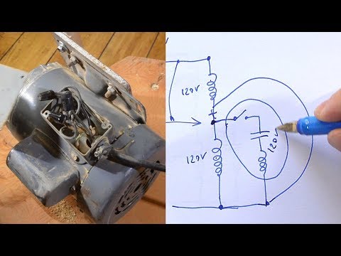
Assortment of 240v motor wiring diagram single phase. Baldor weg leeson duration. Matthias random stuff 59667 views. Internally the motor has two 120 volt windings which are in series when the motor is wired for 240 volts left at left. Longer life may be found due to a stronger motor where as 120 volt motors may heat up more which may affect the over all lifespan of the motor. When switching it to 120 volts the two.
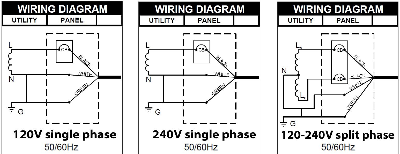
The ground terminal should be a green screw or possibly a green wire. The cable coming into this local box will have both of the 120 volt opposite phases one with black and one with red insulation common with white insulation and a green ground wire which might also be a bare. Step 3 connect the ground wire from the switch to the ground terminal in the wiring box. Wiring diagram pics detail. A balanced electrical load which may save on electricity compared to an unbalanced electrical load. 240 volt motors will have a stronger start compared to a 120 volt motor.
The advantages of a 240 volt motor. It is to be. Partial list of carrierbryantpayne units that use this item. Please contact with any questions you have or any other parts you may need. Ill dispense with the background issues unless you really want to hear the story and post my wiring diagram both for checking and for a better way to do it. For a ground terminal.
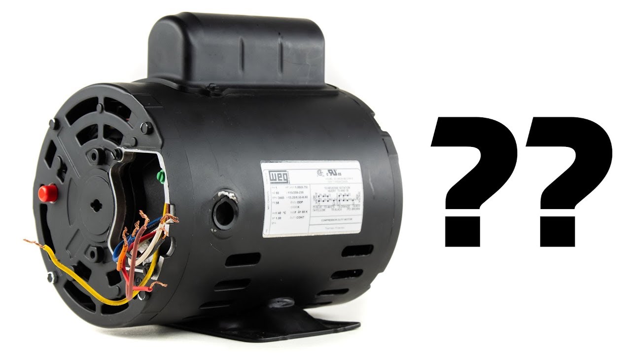
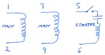
But sometimes when you open up a motor theres just six wires and no diagram. Thus a capacitor start induction run motor produces a better rotating magnetic field than the split phase motors. This is a brand new oem ge genteq carrierbryantpayne furnace x13 blower motor module combination. Stronger performance will definitely be noticed especially. It is important to point out from the phasor diagram that the phase difference between im and is is almost 80 degrees as against 30 degrees in a split phase induction motor. It is evident from the phasor diagram that the current through the starter winding is leads the voltage v by a small angle and the current through the main winding im lags the applied voltage.
Strip the wire ends with a wire stripper and fasten them together with a wire nut. The motor is 5 58 in diameter frame 48y. Theres so many switch types and incomplete switch and motor information that its difficult to reach a solid conclusion for a wiring. The longer the wire the more significant these losses become. Wiring a single phase 220 volt motor is straightforward. 240v motor wiring diagram single phase single switch wiring diagram 110 single circuit diagrams wire center u2022 rh casiaroc co.
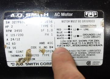
This happened to be the case for the 15 hp motor for my old table saw. Thanks for looking and good luck. Fb4cnf018000abaa 55 fb4cnf018005abaa 55 fb4cnf018008abaa 55 fb4cnf018l00abaa 160 fb4cnf018l05abaa. The best way to change the voltage on a motor is to follow the wiring diagram on the label. Click on the image to enlarge and then save it. Rewiring a motor from 240 volts to 120 volts duration.
Turn off the power at the breaker that supplies the local blind blank flat cover electrical box with the feed that will supply your motor. This is wasted power that is lost in the form of heat. Look at the underside of the cover for the wiring diagram which specifies which wires are used to wire the motor for 240 volts.
Gallery of 120 240 Volt Motor Wiring Diagram