Fresh exhaust fan wiring diagram electrical outlet symbol 2018. Free wiring diagram menu.
How To Wire An Otr Microwave Vent Fan
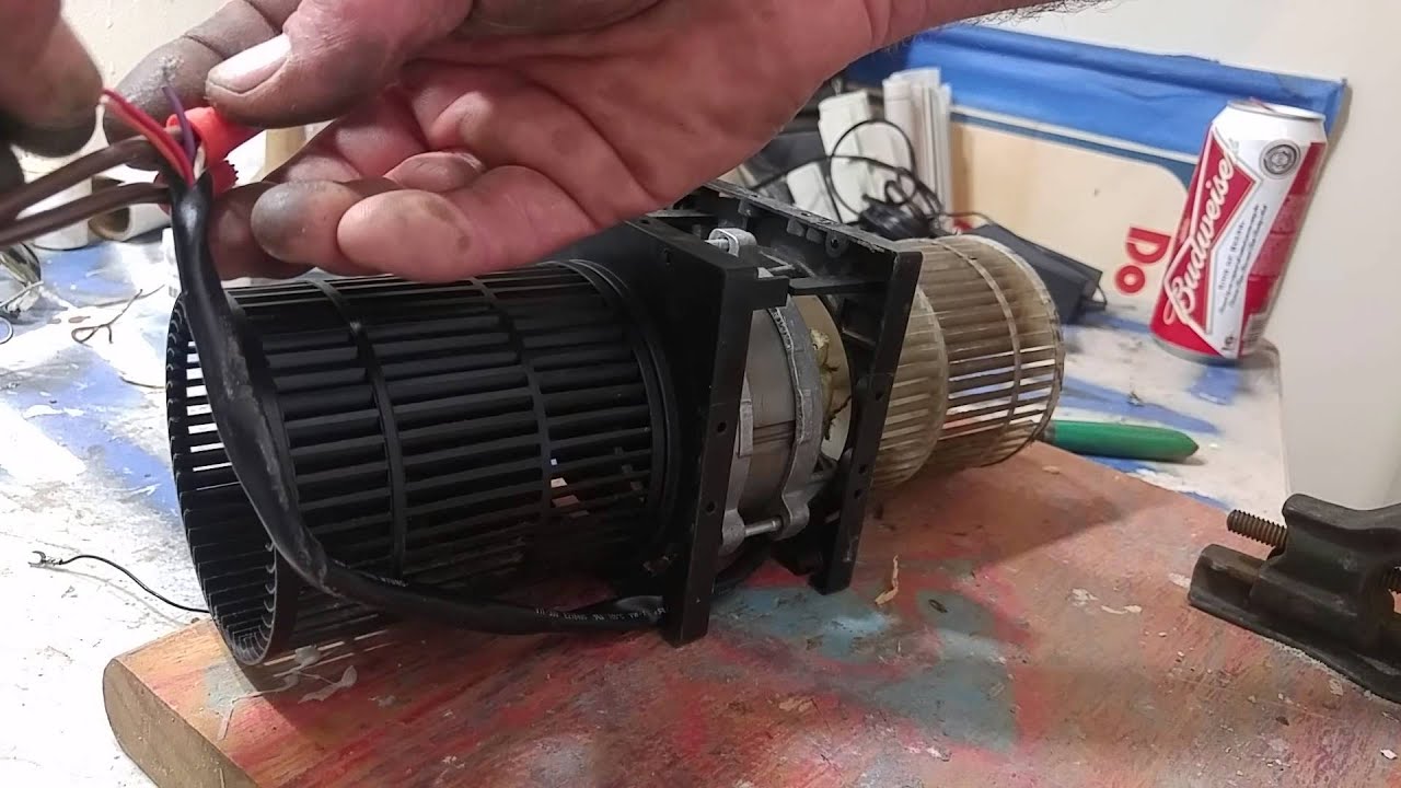
Exhaust fan motor wiring diagram. Dayton exhaust fan wiring diagram by saum hadi posted on august 11 2018 a326 dayton motor wiring diagram library dayton upblast ventilator 12 1 2 in 115 230v 5dvp8 zoro house fan wiring diagram 1 source house fan wiring diagram 1 source shutter mount exhaust fan 12 variable sd 800 cfm. Double check your connections using the fan wiring diagrams. It shows the components of the circuit as simplified shapes as well as the power as well as signal connections in between the gadgets. So im thinking that the motor may have to start with the slower speeds first. Spun aluminum upblast exhaust fans operation instructions and parts manual wire the motor according to the wiring diagram on motor label or on the sticker inside the motor wrap. To check out a wiring diagram first you have to know just what fundamental elements are consisted of in a wiring diagram and which pictorial icons are used to represent them.
A wiring diagram is a simplified conventional pictorial representation of an electric circuit. Checking the motor and capacitor connections. Wall fans with cabinets remove guard from cabinet. All motors should be wired to spun aluminum upblast exhaust fan exploded view. It shows the elements of the circuit as simplified forms and also the power and also signal connections in. A listing of electrical signs and also summaries could be discovered on the electric symbol page.
September 3 2018 february 12 2019 by larry a. Wall fans extend the proper gauge wire to the fan motor. Exhaust fan motor repair खड खड क आवज आन. The common aspects in a wiring diagram are ground power supply cord as well as connection result devices switches resistors logic gateway lights etc. Broan bathroom fan wiring diagram. More about electrical.
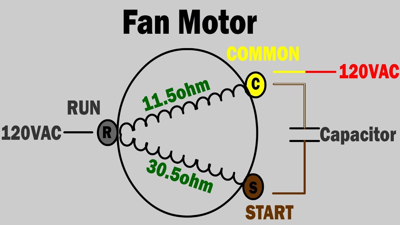
Assortment of broan bathroom fan wiring diagram. Variety of canarm exhaust fan wiring diagram. How to verify fan motor wiring connections. Restrain excess wire from entering the shaft and propeller area. Follow the wiring diagrams on the motor nameplate. From what you are describing you have taken apart the wiring that most likely involves the switch controls for the exhaust fan and the light so you will need to identify the wiring to the switch for the light and the switch for the fan in order to make the correct connections for the fan and light.
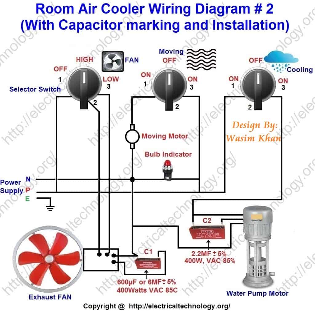
A wiring diagram is a streamlined conventional pictorial depiction of an electrical circuit. A wiring diagram generally offers info concerning the loved one position as. 3ø wiring diagrams 1ø wiring diagrams diagram er9 m 3 1 5 9 3 7 11 low speed high speed u1 v1 w1 w2 u2 v2 tk tk thermal overloads two speed stardelta motor switch m 3 0 10v 20v 415v ac 4 20ma outp uts diagram ic2 m 1 240v ac 0 10v outp ut diagram ic3 m 1 0 10v 4 20ma 240v ac outp uts these diagrams are current at the time of publication. They work just like a dimmer switch with infinite speed. Canarm exhaust fan wiring diagram gallery. And not start in the high speed because the motor or capacitor has not been designed for that type of operation.
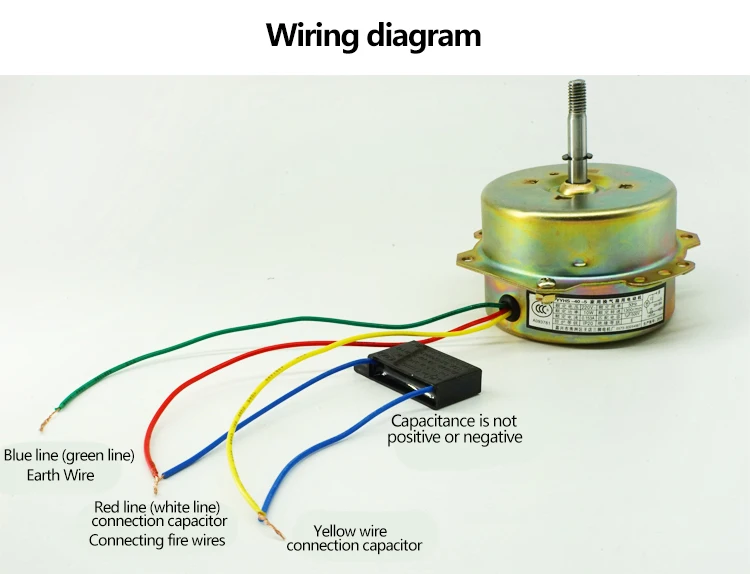
The power source wiring to a typical hood exhaust fan enter a junction box where there are black white and ground or a ground screw terminal. These controls are made to mount in a single gang box on the wall. So with that connection its color to color. Broan exhaust fan wiring diagram valid bathroom fan motor wiring. Have to be removed in order to make the connections in the motor terminal box. All canarm brand ceiling fans shown on this page are made to work with solid state speed controls.
How to connect fan coil easy 5 wire ac fan motor wiring diagram 3 speed duration. You should see that there is a separate motor winding for high speed. The concern is that there is a capacitor for the motor.
Gallery of Exhaust Fan Motor Wiring Diagram