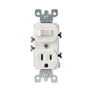
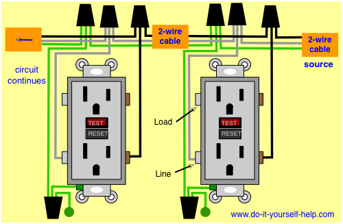
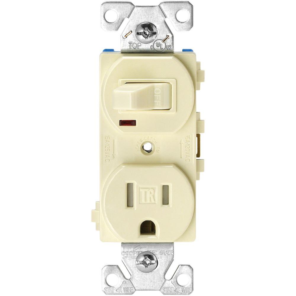
Next we need to check to see if the wall box where the combo plug and switch have the required wires. Instructions for wiring a combo outlet and switch.
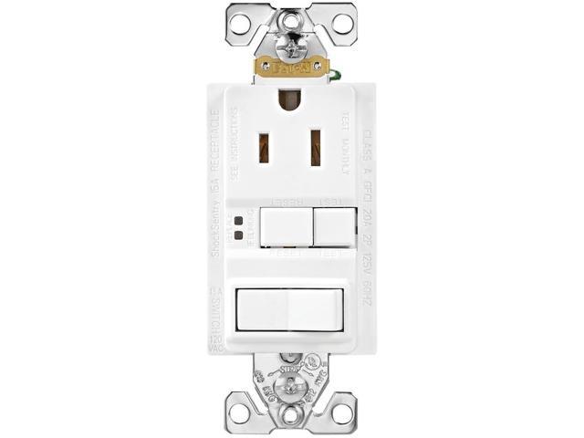
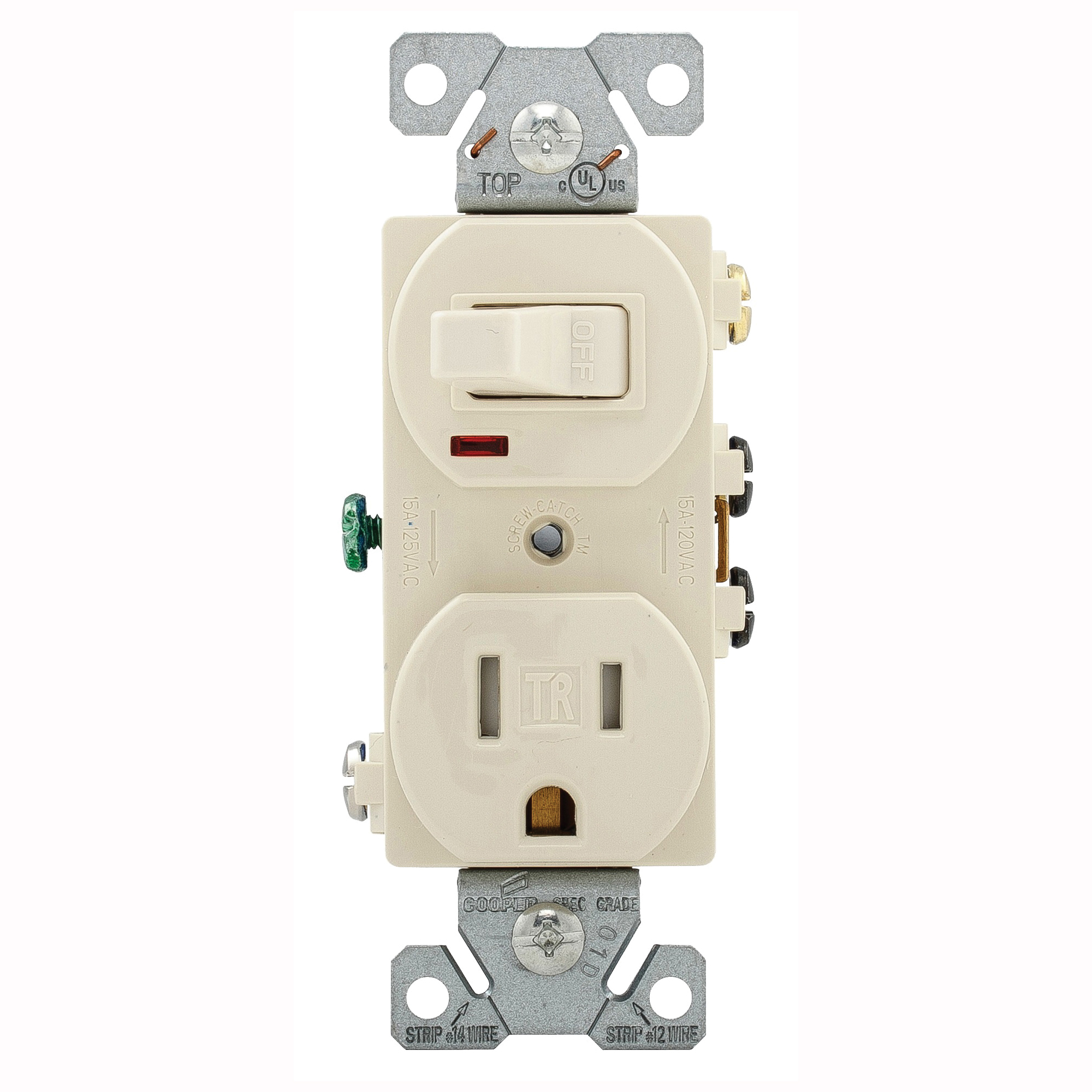
Eaton Cooper Wiring Sgfs Series Sgfs15w Msp Duplex Gfci Receptacle Switch 120 V Switch 125 V Receptacle 1800 W
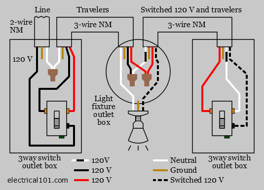
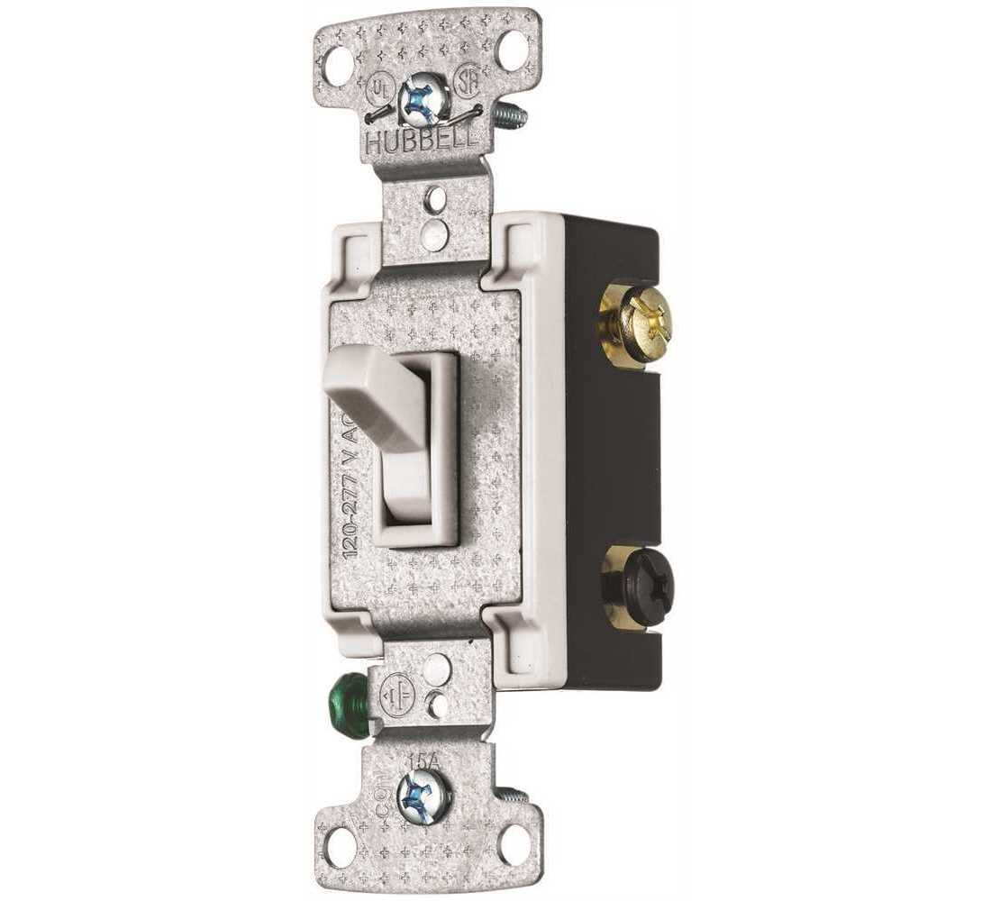
Wiring a 120 volt switch. A single pole single throw switch such as a light. Alternative on off control for a 240 volt pump. It is important to know that a white wire that is found in a switch box is not necessarily a. Set your store to see local availability add to cart. With the screw terminals you will typically have the option of sharing the same power source or separate power sources. A double pole switch has four termination points two for the 240 volt line of the electrical circuit and two for the load which leads to the pump motor.
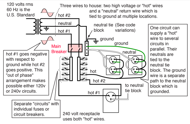
Wiring a single phase 220 volt motor is straightforward. Double check with a meter. First we need to understand that a 120 volt outlet requires a hot neutral and a ground wire. A double pole switch is the safest way to make sure that both lines of the 240 volt circuit power to the pump are turned off. Cap off one of the black wires and only use 1 black wire which should be 120 volt. Leviton 15 amp industrial grade heavy duty 3 way.
120 volt relay wiring diagram beautiful revolution voltage sensitive wiring diagram for a 240 volt relay new electronic relay wiring wiring diagram for changeover relay inspirationa wiring diagram ac new dpdt relay diagram electrical outlet symbol 2018 impulse relay wiring diagram best relay base wiring diagram winch relay wiring diagram new winch solenoid wiring diagram 12 volt a newbie s guide to circuit diagrams. Single phase 220 volt ac motors are really two phase 240 volt motors especially when compared to three phase 208 volt motors and single phase 120 volt motors. Collection of 120 volt relay wiring diagram. How to wire a gfci combo switch receptacle outlet the same is true for the gfi outlet connections. It reveals the parts of the circuit as streamlined shapes and the power as well as signal connections between the devices. A wiring diagram is a simplified traditional photographic representation of an electrical circuit.
Wiring a control switch for a 240 volt pump. The hot wire in a 120 volt residential ac circuit usually is coated with black insulation while the return or neutral wire is white. This gfi switch combo will either come with wired leads for connecting to your existing wires or there will be screw terminals for direct wired connections of your existing wires. An initial look at a circuit diagram might be confusing but if you can. When controlling a 240 volt motor it is best to install a double pole switch for this irrigation pump. This is because the motors single phase actually operates on the difference between the two 120 volt phases that comprise the residential 240 volt input.
Gardner bender toggle switch spst sb 6 amp 120 volt ac case of 5 model gsw 124 26 49 case 26 49 case free delivery with 45 order. A relay contactor. Sounds like the 2 black wires are for 220 volt motor and your wiring in a 120 volt motor.
Gallery of Wiring A 120 Volt Switch