It is important to point out from the phasor diagram that the phase difference between im and is is almost 80 degrees as against 30 degrees in a split phase induction motor. Motor will operate satisfactorily on line voltage within 10 of nameplate voltage.

Mars Motors Wiring Diagrams C3 Wiring Diagram
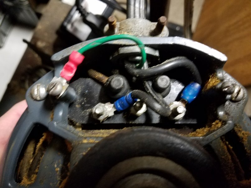
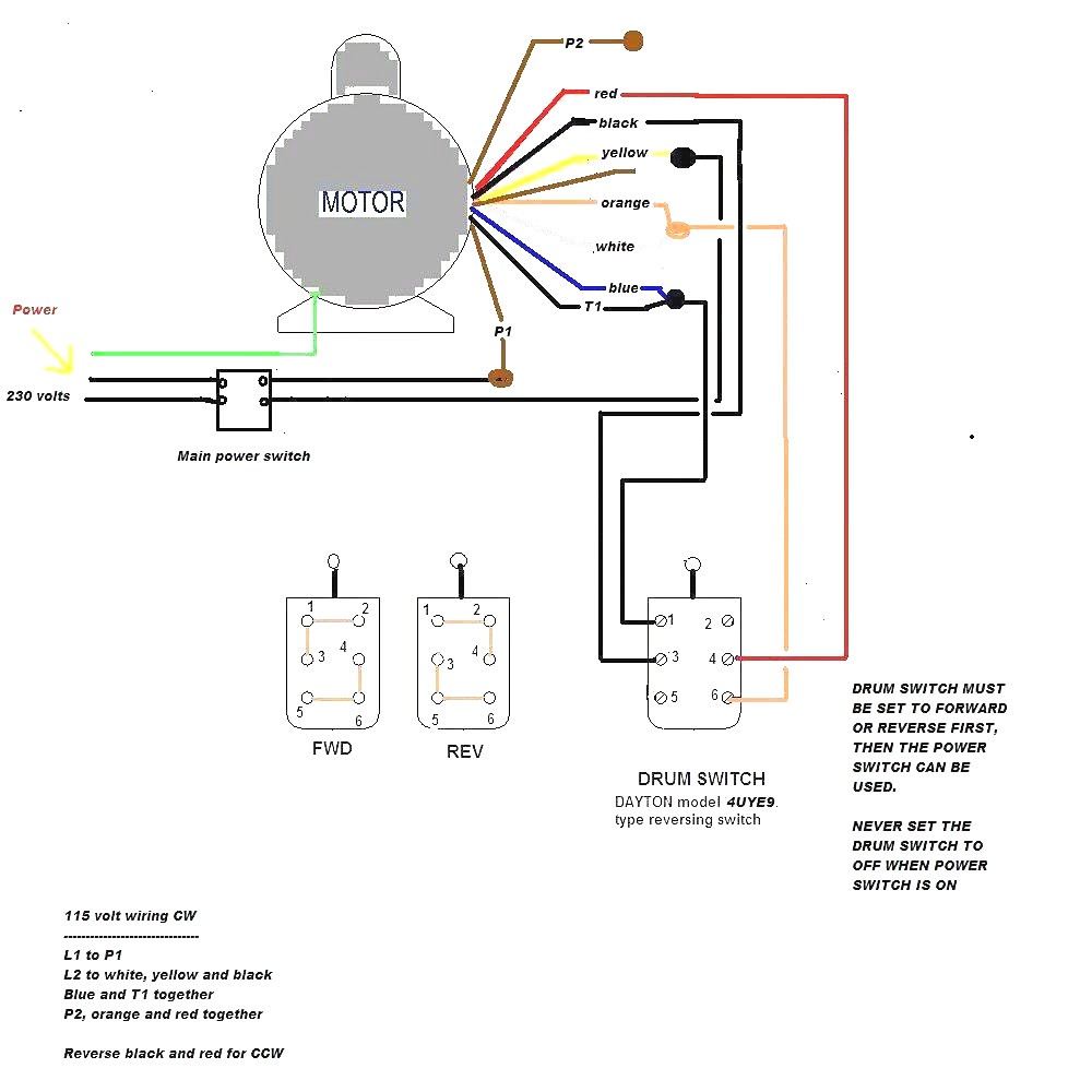
Westinghouse single phase motor wiring diagram. I am glad for that but i wish it turned in the opposite direction. The reconnection must be carried out by qualified electrician. 115 use with 170 mfd capacitor. Rpm 17251140 12 hp 115v 60hz thermally protected l type. The previous owner ran the motor off of a 2 prong plug with no ground. Larry was a professional flea marketeer whom i bought a lot of tools stuff from over the years.
It seems to me that the terminals are bypassed as the power cord is directly connected to the motor. Single phase motor wiring diagram forward reverse single phase motor reverse and forward connection with capacitor wiring diagram. I would like to fix this. That impression westinghouse single phase motor wiring diagram mars motors above is actually labelled along with. In this video i talk about how to go about wiring a motor that was never supplied with a wiring diagram. Larry assured me it would run just fine.
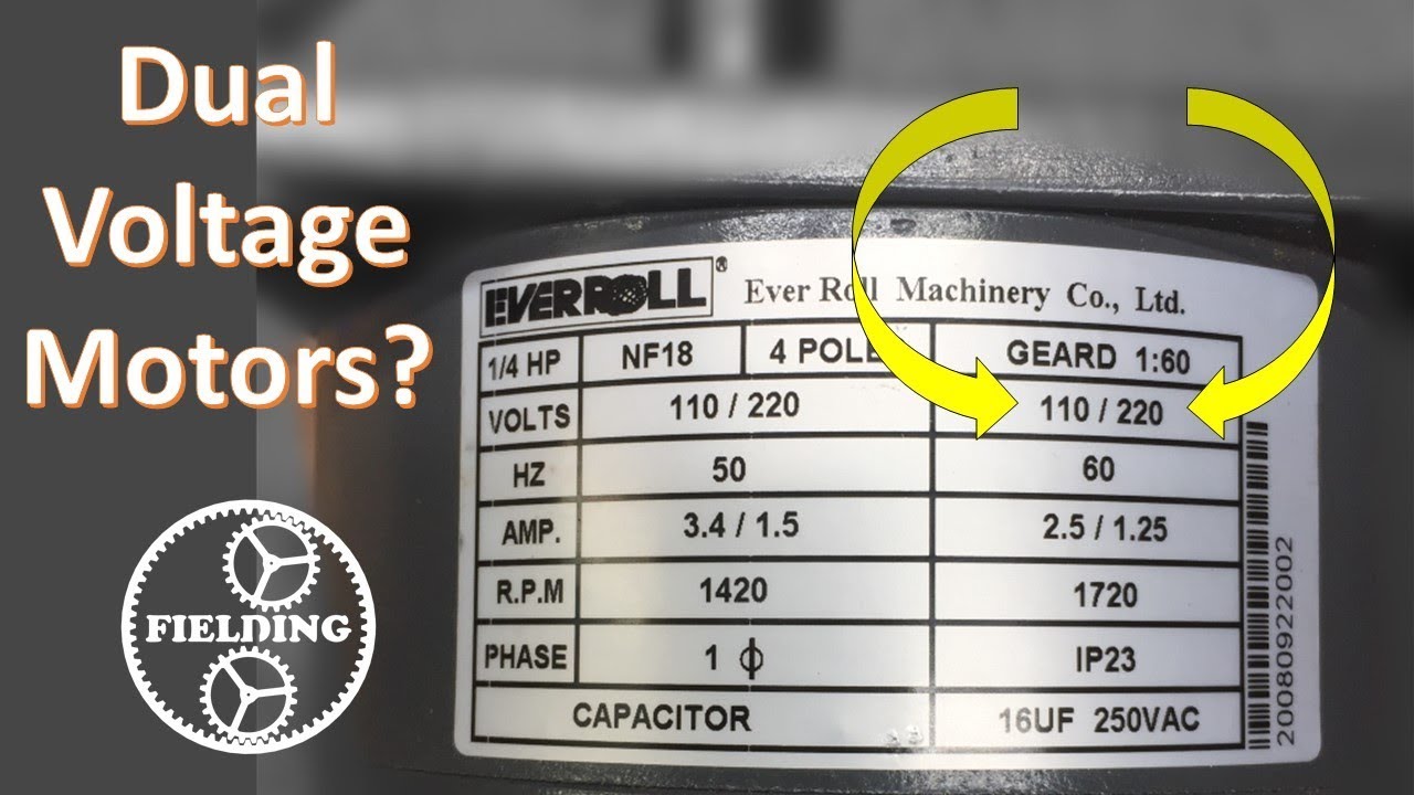
Motor sits behind the press under the. Westinghouse electric motor manufactured in 76. I want to revive this motor by adding the proper ground wire and wiring in an onoff switch at the press not at the motor. Nameplate voltage and frequency should agree with power supply. Thus a capacitor start induction run motor produces a better rotating magnetic field than the split phase motors. Frequent stopstarts andor changing of the direction of rotation will damage the motors capacitors and winding.
The motor is separate from the press and is an addition that most printers added to run the press via belt and flywheel to make printing much quicker. The story was he bought this motor from some old guy who told him he had it wired at lubbock electric. It is to be. Or frequency with 5 and with a combined variation not to exceed 10. With it came an old westinghouse 12 hp 1725rpm motor 115 volts serial. Wiring diagram single phase motors 1empc permanent capacitor motors 1empcc capacitor start capacitor run motors electric motors limited when a change of direction of rotation is required and a change over switch is to be used it will be necessary to reconnect the termination on the terminal block.
230 volt motors can be used on 208 volt network systems but with slightly modified performance characteristics as. Assortment of single phase motor wiring diagram forward reverse. These tips can be used on most electric motor brands such as weg baldor. Wiring of motor and control overload protection and grounding should be in accordance with national electrical code and all local safety requirements. Click on the image to enlarge and. I bought it from an old friend about ten years ago for 40.
Circuit diagram of single phase motor starter connection diagram of single phase motor starter single phase motor contactor wiring diagram. Ive got an electric split phase motor no capacitor with a centrifugal switch. Published by means of wiringforums with september 5 2017. Wiring diagram images detail. I have this 2hp 230 volt 1725 rpm westinghouse motor that someone re wired to run on 115 volts and to my surprise it does. In this video jamie shows you how to read a wiring diagram and the basics of hooking up an electric air compressor motor.
It is evident from the phasor diagram that the current through the starter winding is leads the voltage v by a small angle and the current through the main winding im lags the applied voltage.
Gallery of Westinghouse Single Phase Motor Wiring Diagram