Ic1 2 oesap. On a star delta system is there ever a time when a single phase might go between a single winding eg.

Star Delta Starters Explained The Engineering Mindset
U1 v1 w1 colours. How do you know if the copper links between u1 v1 w1 and u2 v2 w2 on a dol motor are to be installed vertical or horizontal. 3 phase winding for 2 voltages delta connection l1 l2 l3 t1t2 yegn 7 rd y l1 t1t2b1b2 8 wh u1 w1 u2 v1 3 motor w2 v2 tc l2 l3 5 or 3 gy 4 bu 2 bk 6 vi 1 bn m45 fig. Rotation u can mark r to u1 y to v1 and b to w1. L1 and l2 go between u1 and u2 l2 and l3 go between v1 and v2 and l3 and l1 go between w1 and w2. 3 phase winding for 2 voltages star connection l1 l2 l3 t2t1 yegn 7 rd y l1 t1t2b1b2 8 wh u1 v1. U1 w1 u2 v1 3 motor w2 v2 tc l2 l3 5 or 3 gy 4 bu 2 bk 6 vi 1 bn m44 fig.
Change direction in clockwise 1 r phase connected to u1 w2 r phase connected to u1 v2 y phase connected to v1 u2 y phase connected to v1 w2 b phase connected to w1 v2 b phase connected. 22033kv voltage level having. How to change rotation of motor in clockwise direction no present motor connection. U1 w1 v1 u2 w2 v2 t1 t2 high voltage y high voltage y high voltage y low voltage thermal potector l1 r l2 s l3 t l1 r l2 s l3 t l1 r l2 s l3 t u1 u5 w1 w5 v1 v5 w1 w2 t1 f2 terminal board motorized pulley 230v thermal potector l1 r l3 t low voltage low voltage yy rectifier terminal board u1 w1 v1 t1 t2 thermal potector l1 r l3 t u2 w2 u5 w5 v2 v5 external connection diagrams for motorized pulleys terminal box 55 kw 132 kw electromagnetic brake execution. More electrical engineering interview questions. Gamma ec d 5051 diags.
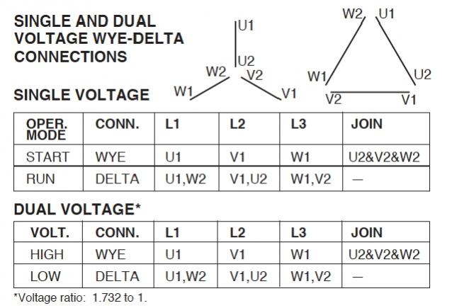
Ic1 2 ocdeecvglgl gamma ec d 5253 diags. From this triangle diagramwe can determine the correct phasecable termination for right terminal and the rotationas we knowthe star. L1 goes between u1 and u2 i dont think so from recent experience but my understanding of 3 phase motors would have each winding as a single. U1 v1 w1 w2 u2 v2 tk tk thermal overloads two speed stardelta motor switch m 3 0 10v 20v 415v ac 4 20ma outp uts diagram ic2 m 1 240v ac 0 10v outp ut diagram ic3 m 1 0 10v 4 20ma 240v ac outp uts these diagrams are current at the time of publication check the wiring diagram supplied with the motor. Is this answer correct. These diagrams apply to intelligent control motorsthat are fitted to the following products pgs ocdeec.
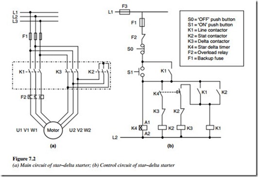
For detail about star delta stater please read my last post about it. For star delta staterthe motor connection must have 6 cables from control panel and 6 terminals at induction motor u1u2v1v2w1w3to wiring the motor connection for star delta starterthe important thing that we must fully understand is about the basic of star delta magic triangle. The rest u2v2 and w2 will be at the star pointnow u can mark as u2v2 and w2 at the other ends of each u1v1 and w1if u know about phase sequence very well u will find that motor terminals are not importantimportant thing is which rotation we need and how we will feed to get right rotation we want.
Gallery of U1 V1 W1 Colours


/SPR_1152863-electrical-wire-color-coding-5afca004fa6bcc0036b72fd5.png)