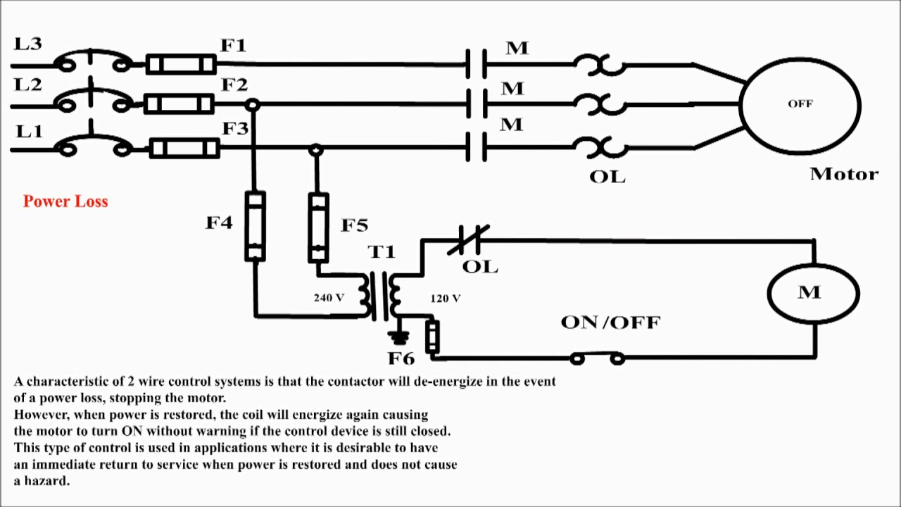
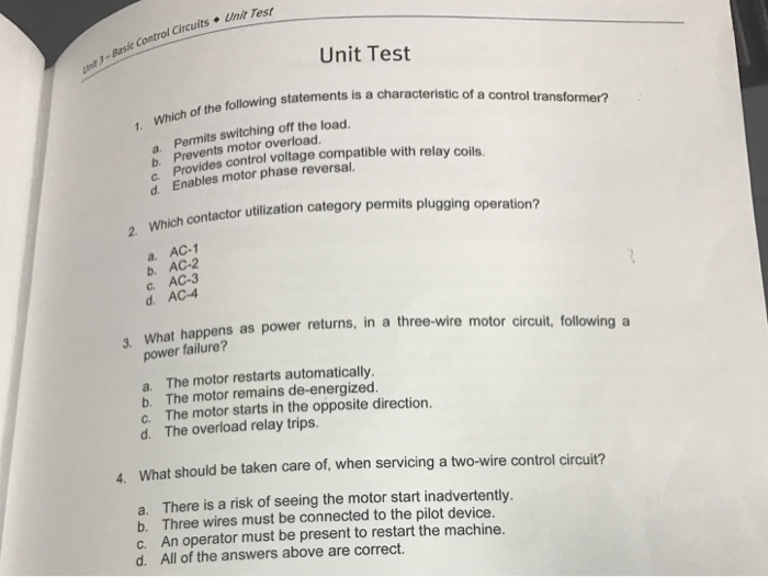
If the power failure occurs the motor turns off. Exception 2 to sec.

3 Way Light Switch Using A Two Wire Control Light Wiring
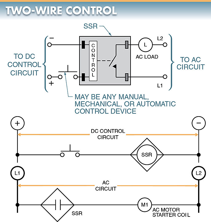
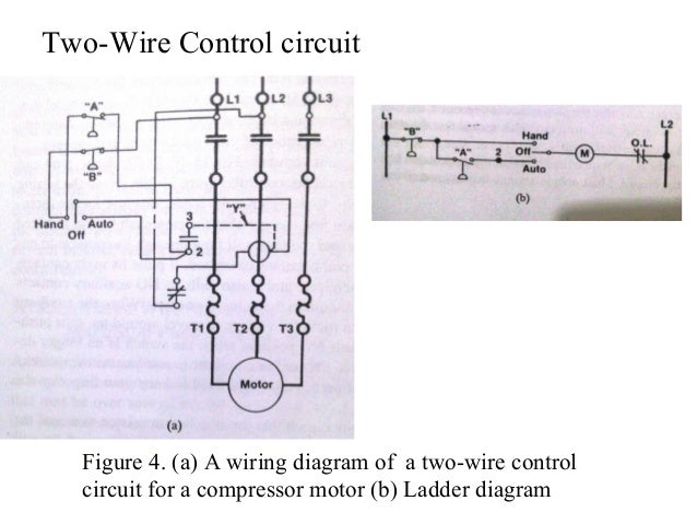
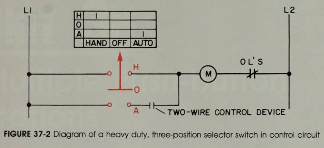
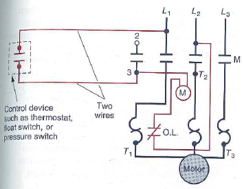
Two wire control circuit. Two wire control circuits are so named because only two wires are required to control the operation of the circuit. This circuit is a basic control for a hot water boiler. Go to the control and power wiring lesson series to select your next lesson. This may include such applications as sump pumps tank pumps electric heating and air compressors. The control contact may be a level switch contact or a temperature switch contact. Two wire circuits may incorporate several different external sensing devices as shown in figure 18 4.
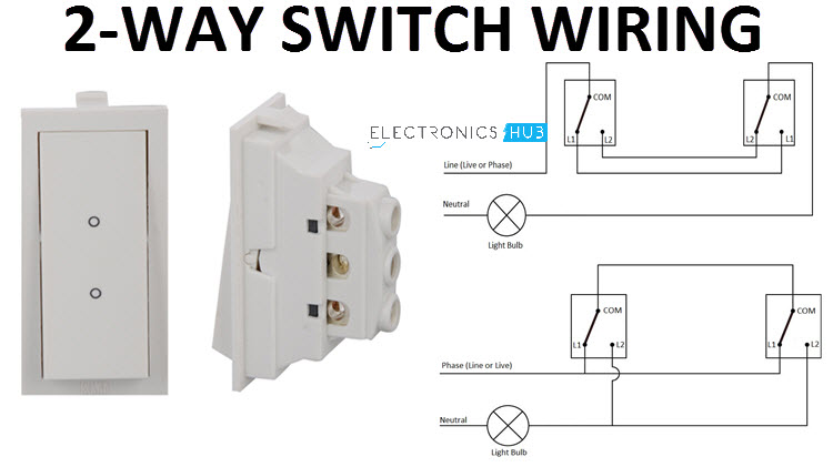
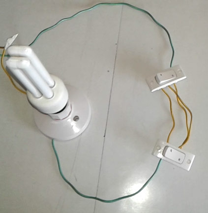
In this video we show you how to wire a 2 wire control circuit to a relay and a light. The com terminal of the second switch is connected to one end of the light bulb while the other end of the light bulb is connected to the neutral of. Two wire control as seen in configuration 1 consists of a control device containing one set of contacts used to facilitate the on an off operation of a pilot device. The contactor k remains energized as long as the control contact is in a close condition. One example is when the power supply conductors and control circuit conductors are run in the same conduit to control and operate the same piece of equipment such as a motor controller. Not all transmitters can be wired in this format and must be specifically designed to accommodate this configuration.
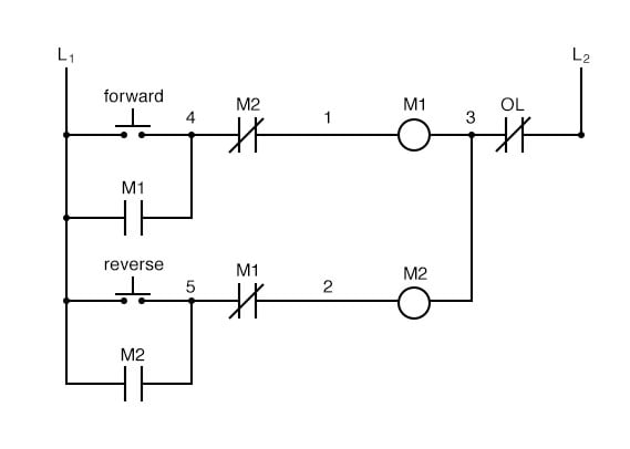
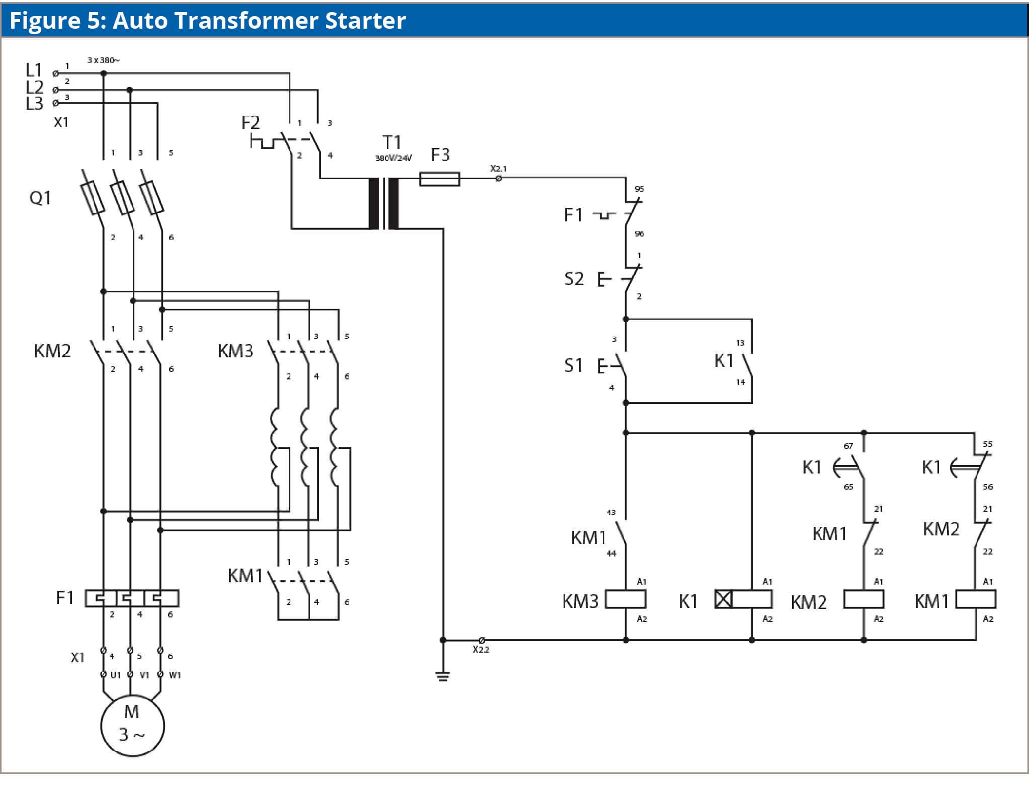
When the 24vdc relay energizes it pulls in the r1 contactor that feeds three phase power to the motor. The basic control circuits include two wire three wire controls manual automatic sequential control stopstart forward reverse and jogging circuits. See image below for an example of 2 wire control being used to pull in a contactor to start a 3 phase motor. Exception 1 to sec. Coming to the com terminals the com terminal of the first switch is connected to phase or line or live. In these systems one typically closes a disconnect switch or circuit breaker to energize the circuit and the actual energizing of the motor in the system is controlled by the operation of the pilot device.
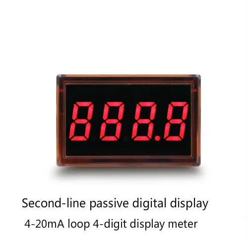
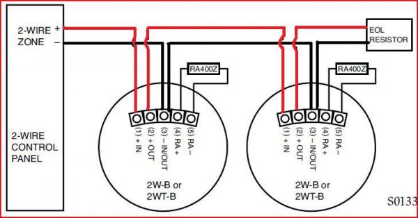
Two wire loop powered transmitters. L1 terminals of both the switches are connected together and l2 terminals of both the switches are also connected together. Coming to the actual wiring the following schematic shows the implementation of a two wire control two way switch. Only two cable cores are required to the transmitter. Two wire controls are generally designed to carry small amounts of current. Has low power consumption.
Am i missing something. This type of control system cannot sufficiently handle large amounts of. Two float switches are used to sense low and high water conditions in the boiler. If i physically alternate the actual wires to the box i can. The circuit shown in figure 75 can be used for an auto start operation of a motor after a power failure depending on the position of the control contact. This configuration supplies power and 4 20ma signal over a two wire loop connection between the transmitter and the control panel.
The motor will then restart automatically once the power is restored since the control contact is. The thermostat controls the action of the burner. 1 the power supply or class 1 circuit. The turnouts are the standard 2 wire red white and i am using the 5175 momentary control box. A separate power supply is required for both the transmitter and control panel. The circuit is.
725 26b allows mixing for underground conductors in a manhole if you comply with all of the following conditions. The two wire control circuit is commonly used in applications where the operation of a system is automatic and basically two wires are used to provide voltage to the load. A high limit temperature switch will stop the burner if the water temperature should. I have been attempting but with no success to wire turnouts properly so that they switch in both directions. 725 26b clarifies you can mix these circuits when installed in factory or field assembled control centers.
Gallery of Two Wire Control Circuit