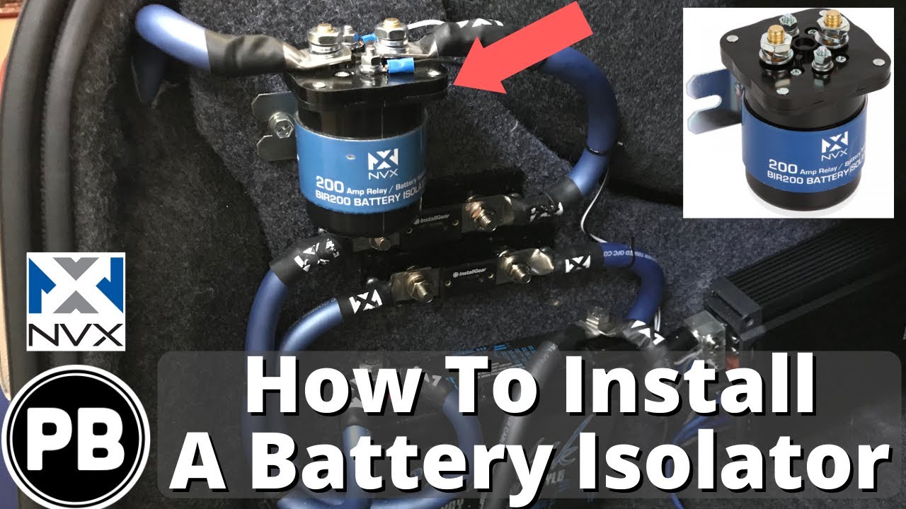
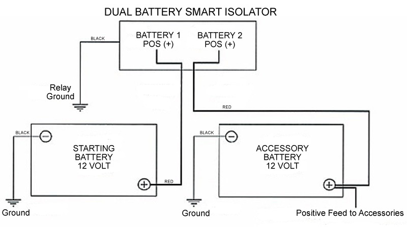
This wire is simply used as a ground for activating the relay. True battery isolator wiring diagram.

Cg 7472 Battery Isolator Wiring Diagram Battery Switch
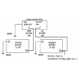
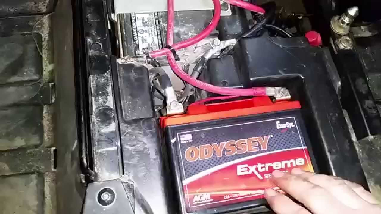
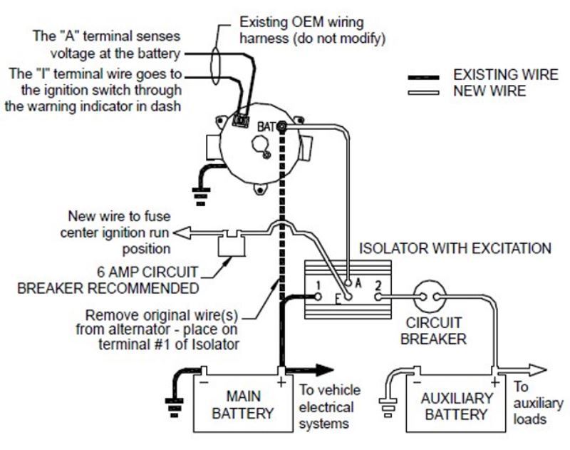
True battery isolator wiring diagram. Connect a cable from the positive terminal of the primary battery by removing one of the nuts of the threaded studs on the back of the isolator. A wiring diagram is a type of schematic which uses abstract photographic signs to show all the interconnections of components in a system. Wiring is accomplished by. Wiring diagram wiring the relay. Icons that stand for the parts in the circuit and lines that represent the connections between them. After answering numerous questions about different battery isolator schemes i decided it would be easier to just build a webpage.
Electrical wiring diagrams are made up of two points. Dual battery isolator schematic. The black wire coiled inside the relay needs terminated to a good ground location using the included blue crimp connector. True battery isolator wiring diagram. One terminal on the relay should be connected to the positive terminal of the primary starting battery using 6ga red wire. Assortment of true battery isolator wiring diagram.
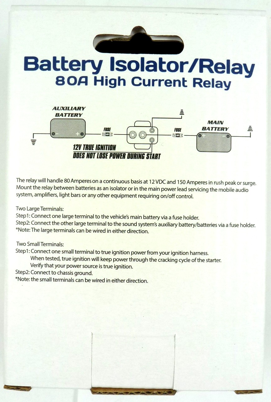
Multi battery isolator wiring diagram true battery isolator wiring diagram download dual battery isolator wiring diagram collection boat dual battery. A wiring diagram is a simplified standard photographic depiction of an electric circuit. Below you will find the basic design of 3 types of battery isolators with the pros and cons of each. The dual sensing feature of this battery isolator makes it impossible to install backwards. The isolator from wwwdfnainfo is the simplest of all isolators to install. It reveals the components of the circuit as streamlined shapes as well as the power and also signal connections between the tools.
Gallery of True Battery Isolator Wiring Diagram