The permanent live wire is wired into the switch and the switched live into the switched live terminal. The hot and neutral terminals on each fixture are spliced with a pigtail to the circuit wires which then continue on to the next light.

20 Elegant Switched Live Wiring Diagram
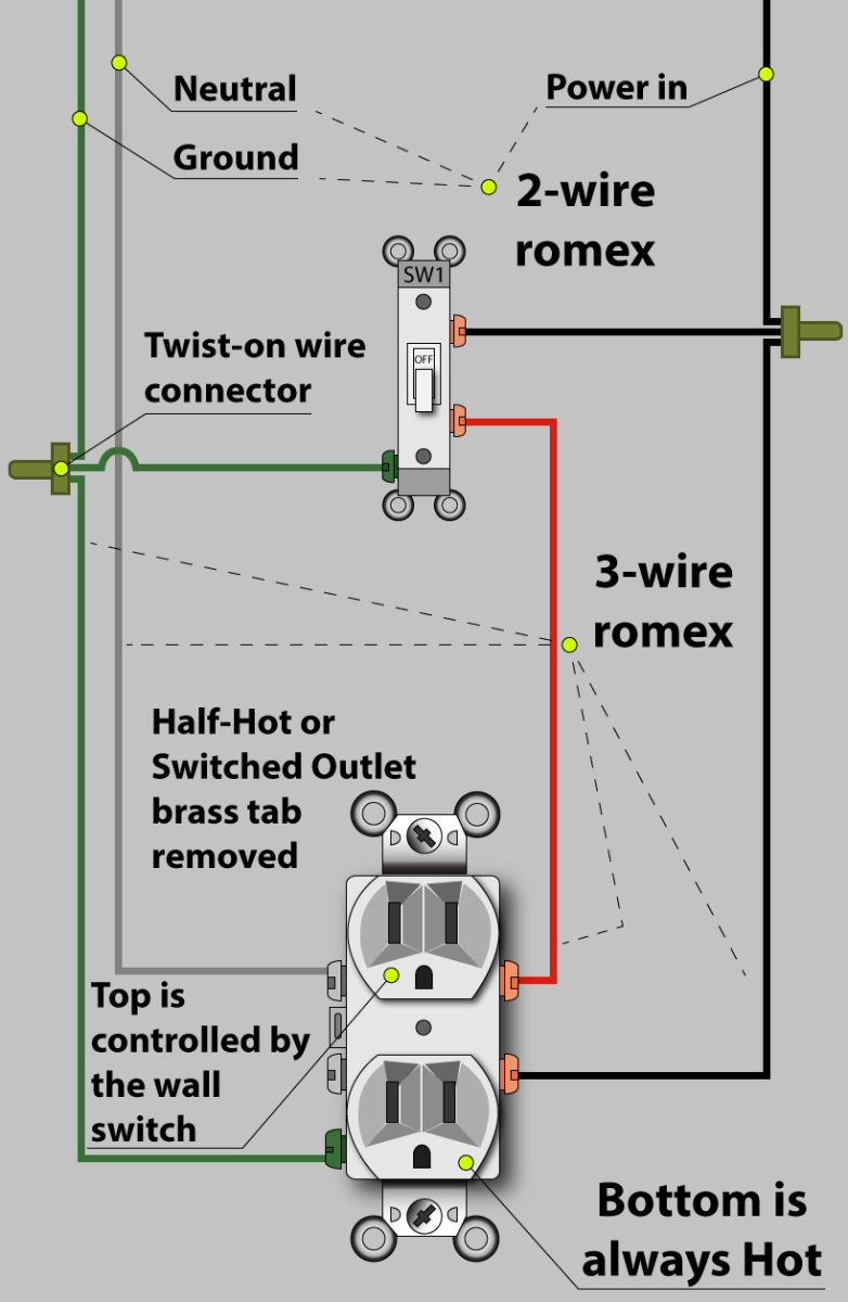
Switched live wiring diagram. In the wiring diagram above a hot and a neutral enter the single pole switch box. The connections for a switched outlet also known as a half hot plug. Before undertaking any electrical project it is imperative that you know precisely what it is youre doing and to keep in mind that electricity can kill. With that said this electrical tutorial presents a guide to identifying the switched live wire on a lighting circuit and also explains how to rewire a ceiling rose. The source is at the outlet and a switch loop is added to a new switch. The diagram shows the power entering into the circuit at the switch box location then sending one power line for the outlet which is hot all the time and a switched leg for the top half of the outlet being used for a table lamp or a floor.
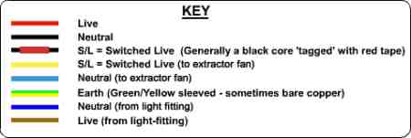
The blue wire is known as the switched live and takes power to the light. Instead of taking the feed wire from the consumer unit to the ceiling rose it is taken to the switch. From there a 3 conductor cable is installed to a switched electrical receptacle outlet. A two conductor cable is installed from the switched outlet to feed an outlet that is live at all times. The black wire from the switch connects to the hot on the receptacle. A 2 wire system includes two wires live and switched live.
Switched live is only live when the switch is on this is where it gets its name from. The black wire power in source attaches to one of the switch screw terminals. The hot source wire is removed from the receptacle and spliced to the red wire running to the switch. This is an alternative way of wiring a lighting circuit. This simple diagram below will give you a better understanding of what this circuit is accomplishing. This diagram illustrates wiring for one switch to control 2 or more lights.
The source is at sw1 and 2 wire cable runs from there to the fixtures. The neutrals are connected together using a terminal connector. For detailed step by step instructions on completing this home project. Fixture wiring exits the switch box. The black wire power out wiring attaches to the other switch screw terminal. Switched receptacle outlet wiring diagram depicting the electrical power feeding into an electrical receptacle box and then going to a switch and to another receptacle.
The wiring and connections will depend on where the power enters the circuit. Circuit electrical wiring enters the switch box. When wiring a 2 way switch circuit all we want to do is to control the black wire hot wire to turn on and off the load. Black wire power or hot wire white wire neutral bare copper ground. A standard 2 wire lighting system. Outlets are split wired so that the top half of the receptacle is live all of the time and the bottom of the receptacle is controlled by the wall switch.
This wiring diagram illustrates adding wiring for a light switch to control an existing wall outlet. A standard 2 wire lighting circuit is shown in figure 1. The brown wire is live also know as permanent live this brings the live supply to the switch. Switch wiring shows the power source power in starts at the switch box. The switched outlet wiring configurations show two different wiring scenarios which are most commonly used.
Gallery of Switched Live Wiring Diagram