Parts from slater electric inc. Found 115 products 1 2 3 description.

Manufactured Home Light Switch Replacement Doityourself Com
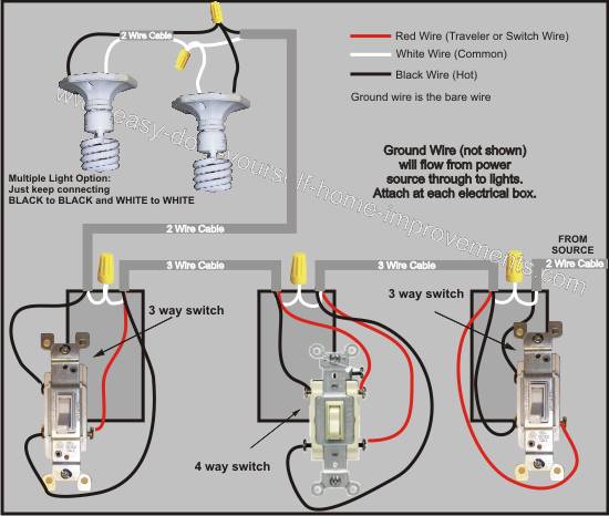
Slater switch wiring diagram. This diagram illustrates the wiring for a circuit with 2 gfci receptacles followed by a light and switch. Be advised that for diagram 2 layouts you will have to adjust my instructions accordingly. This might seem intimidating but it does not have to be. 3 way switch wiring diagram. Pick the diagram that is most like the scenario you are in and see if you can wire your switch. The two hot wires of three wire cable connect to a pair of brass colored traveler terminals on each switch.
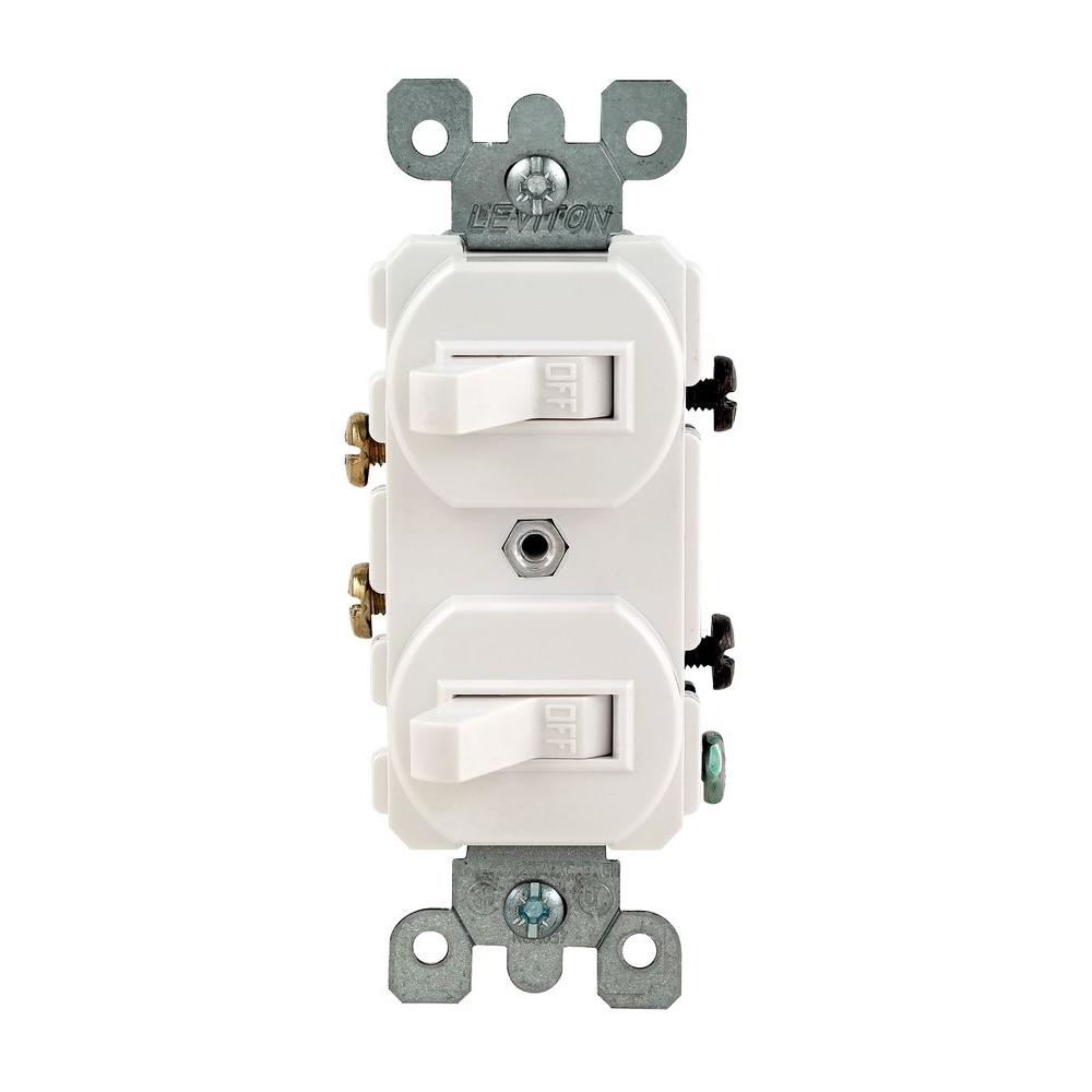
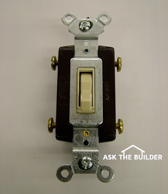
Semiconductor devicediode 5961 00 993 2238 1n941. This circuit is wired the same way as the 3 way lights at this link. Three wire cable runs between the switches and the outlet. If your wiring matches my description diagram 1 or whats shown in diagram 2 above then proceed. This is a completed circuit. A double switch has 2 switch levers in a single housing.
From electrical switches and receptacles to gfci outlets and usb chargers pass seymour electrical wiring devices connectors and outlets are designed to work for you. Lets assume the load you are controlling is a light. Autrol us smart gauge and absolute pressure differential pressure temperature transmitters with hart push button interface and local lcd display krohne radar and ultrasonic level transmitters vibration level switches temperature. I show how to wire a double switch that operates a light and an exhaust fan. This is in the chicago area with conduit. This gfci wiring method may be found in a bathroom or kitchen where the switch may be near a water source.
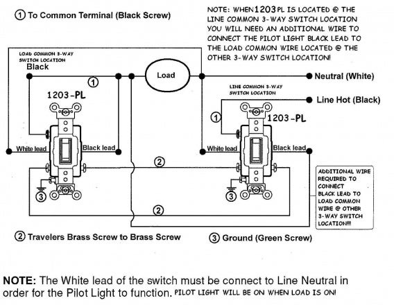
And these innovations can be found in countless commercial residential and industrial electrical wiring installations. 3 way switched outlet wiring. In this diagram the incoming hot wire attaches to the first switchs common dark colored terminal. By connecting the switch to the load terminals on the last gfci the switch and light are protected against ground faults as well. The most common. With these diagrams below it will take the guess work out of wiring.
By wiring a 2 way switch the circuit below shows the basic concept of electricity flow to the load. The source is at the sw1 where the hot is connected to. In this diagram two 3 way switches control a wall receptacle outlet that may be used to control a lamp from two entrances to a room. This 3 way switch wiring diagram shows how to wire the switches and the light when the power is coming to the light switch. The electricity flows from the hot wire black through the 2 way switch shown in off position and then to the light and returns through the neutral wire white. Mechanical electronic pressure level switches transmitters.
Take a closer look at a 3 way switch wiring diagram.
Gallery of Slater Switch Wiring Diagram