According to earlier the lines in a single phase motor wiring diagram with capacitor represents wires. It reveals the components of the circuit as simplified forms as well as the power as well as signal links in between the tools.
Electrical Winding Wiring Diagrams June 2014
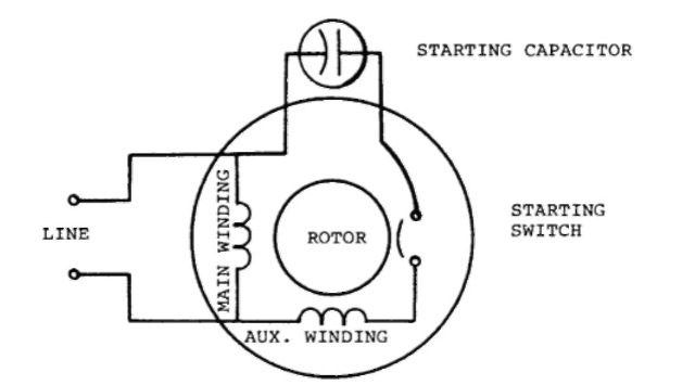
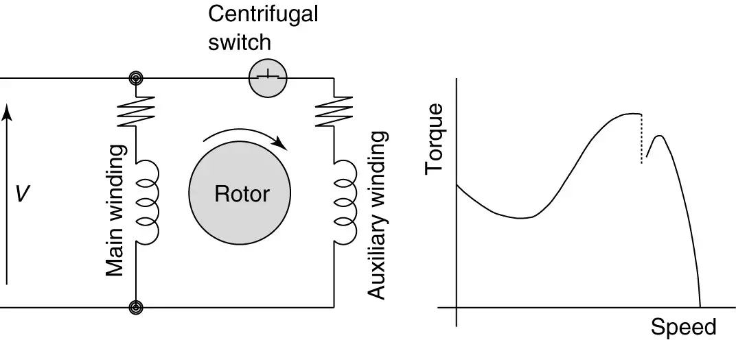
Single phase motor winding diagram. A wiring diagram is a simplified conventional pictorial representation of an electrical circuit. In the single phase induction motor we have two types of winding. Occasionally the wires will cross. This simple no capacitor arrangement serves well for. In which one is called main winding also known with running winding. It also serves to distinguish the single phase motor schematic diagram from that of the quarter phase motor in which the rotor is never represented approved as nema standard 11 16 67.
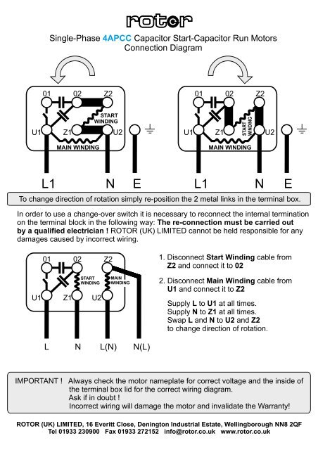
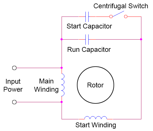
This type of motor is designed to provide strong starting torque and strong running for applications such as large water pumps. And 2nd winding is called auxiliary winding also known with. This post is about the single phase motor winding resistance. Construction of single phase induction motor. Capacitor start capacitor run induction motors are single phase induction motors that have a capacitor in the start winding and in the run winding as shown in figure 12 and 13 wiring diagram. The main winding and starting or auxiliary winding connection shown.
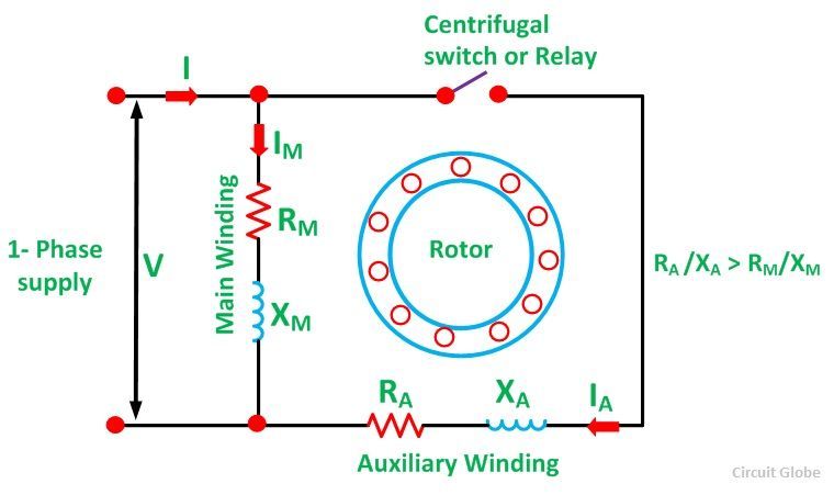
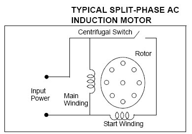
This post is about the single phase 4 pole induction motor winding diagram with centrifugal switch. Single phase motor wiring diagram with capacitor start. Variety of single phase motor wiring diagram forward reverse. This coil produces a moderate starting torque which is disconnected by a centrifugal switch at 34 of synchronous speed. Thus a capacitor start induction run motor produces a better rotating magnetic field than the split phase motors. It is important to point out from the phasor diagram that the phase difference between im and is is almost 80 degrees as against 30 degrees in a split phase induction motor.
However it does not imply link between the cables. With lower inductance and higher resistance the current will experience less phase shift than the main winding. And how to connect the both winding with one another. How to connect. It is evident from the phasor diagram that the current through the starter winding is leads the voltage v by a small angle and the current through the main winding im lags the applied voltage. Injunction of two wires is usually indicated by black dot in the intersection of two lines.
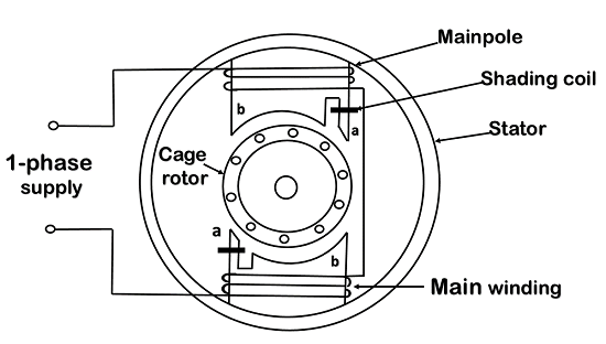
A single phase induction motor is similar to the three phase squirrel cage induction motor except there is single phase two windings instead of one three phase winding in 3 phase motors mounted on the stator and the cage winding rotor is placed inside the stator which freely rotates with the help of mounted bearings on the motor shaft. If an auxiliary winding of much fewer turns a smaller wire is placed at 90electrical to the main winding it can start a single phase induction motor. It is to be. The rotor of a single phase motor is represented by a circle even though there are no external connections to it. Types of single phase induction motors electrical a2z single phase induction motors are traditionally used in residential applications such as ceiling fans air conditioners washing machines and refrigerators single phase motor wiring with contactor diagram the plete guide of single phase motor wiring with circuit breaker and contactor diagram. Or single phase motor with centrifugal switch wiring diagram.
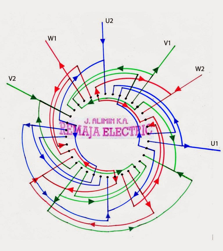
About 30 of phase difference may be obtained. In the single phase 36 slots winding diagram. In this post you will learn about the single phase induction motor winding resistance.
Gallery of Single Phase Motor Winding Diagram