This is a completed circuit. The black wire power in source attaches to one of the switch screw terminals.

3 Way Switch Wiring Electrical 101
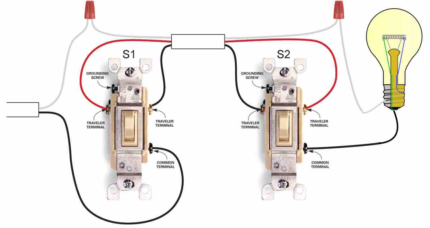
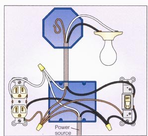
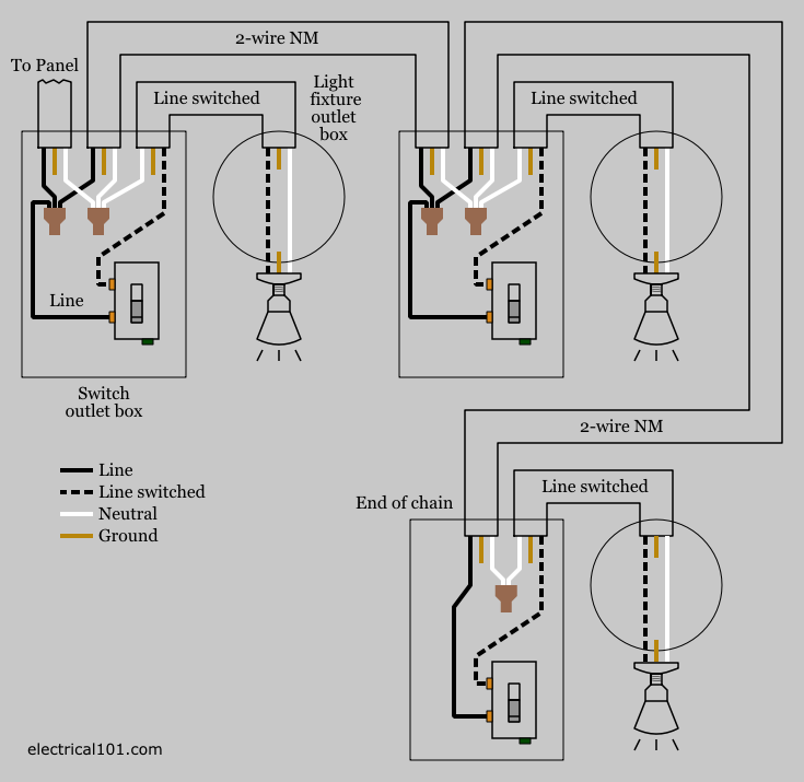
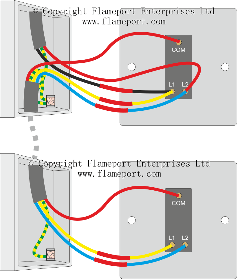
Light switch wiring diagram. The two hot wires of three wire cable connect to a pair of brass colored traveler terminals on each switch. The grounding conductor is not shown in order to simplify the wiring diagram. In the diagram below right a 2 wire nm cable that connects the light fixture to the switch carries 2 line wires one line and one switched line. From the ceiling a three conductor cable with a grounding conductor is used to send power to a light switch. This is a diagram of a switch with a neutral. The photo above depicts the wiring diagram of a ceiling light and light switch with the power from the circuit breaker panel entering the ceiling electrical box.
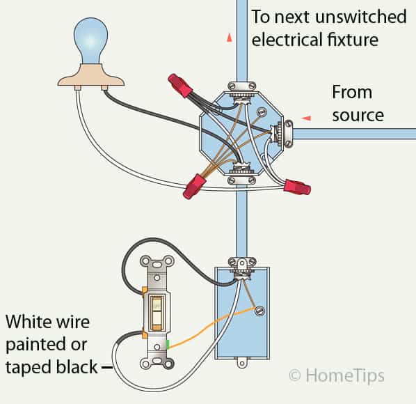
The source is at sw1 and 2 wire cable runs from there to the fixtures. As shown in the diagrams below you can paint a couple of inches of the end of the white wire blackor wrap it with black electrical tapeto. 3 way switch wire diagram power to light switch in this diagram the incoming hot wire attaches to the first switchs common dark colored terminal. When wiring switches this type of cable may be used as a switch legwhere you need two black wires to go from the switch to black wires located at the light or at an intermediate electrical box. The white wire carries line the black wire carries the switched line. The black and red wires between sw1 and sw2 are connected to the traveler terminals.
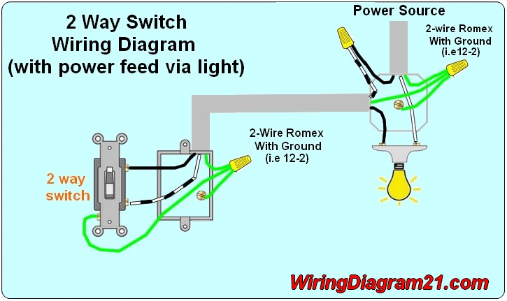
Wiring a single pole light switch. The black hot connection is broken to turn the light onoff the white neutral connection completes the circuit. The bare hopefully solid copper wire is the ground. The black wire power out wiring attaches to the other switch screw terminal. Hey doing it yourself is great but if you are unsure of the advice given or the methods in which to job is done dont do it. The electricity flows from the hot wire black through the 2 way switch shown in off position and then to the light and returns through the neutral wire white.
The fixtures hot wire connects. Wiring diagram 3 way switch with light at the end in this diagram the electrical source is at the first switch and the light is located at the end of the circuit. Multiple light wiring diagram this diagram illustrates wiring for one switch to control 2 or more lights. This light switch wiring diagram page will help you to master one of the most basic do it yourself projects around your house. Three wire cable runs between the switches and 2 wire cable runs to the light. The hot and neutral terminals on each fixture are spliced with a pigtail to the circuit wires which then continue on to the next light.
Since the white wire is hot a black piece of electrical tape is placed on each end. This site is merely. It protects from static build up and from electrical insulation failure in short its only job is to make your home safer. By wiring a 2 way switch the circuit below shows the basic concept of electricity flow to the load. Fixture wiring exits the switch box. Switch wiring shows the power source power in starts at the switch box.
Circuit electrical wiring enters the switch box. Lets assume the load you are controlling is a light.
Gallery of Light Switch Wiring Diagram