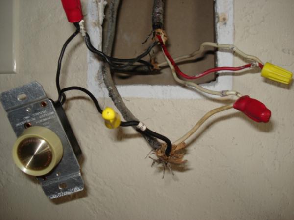
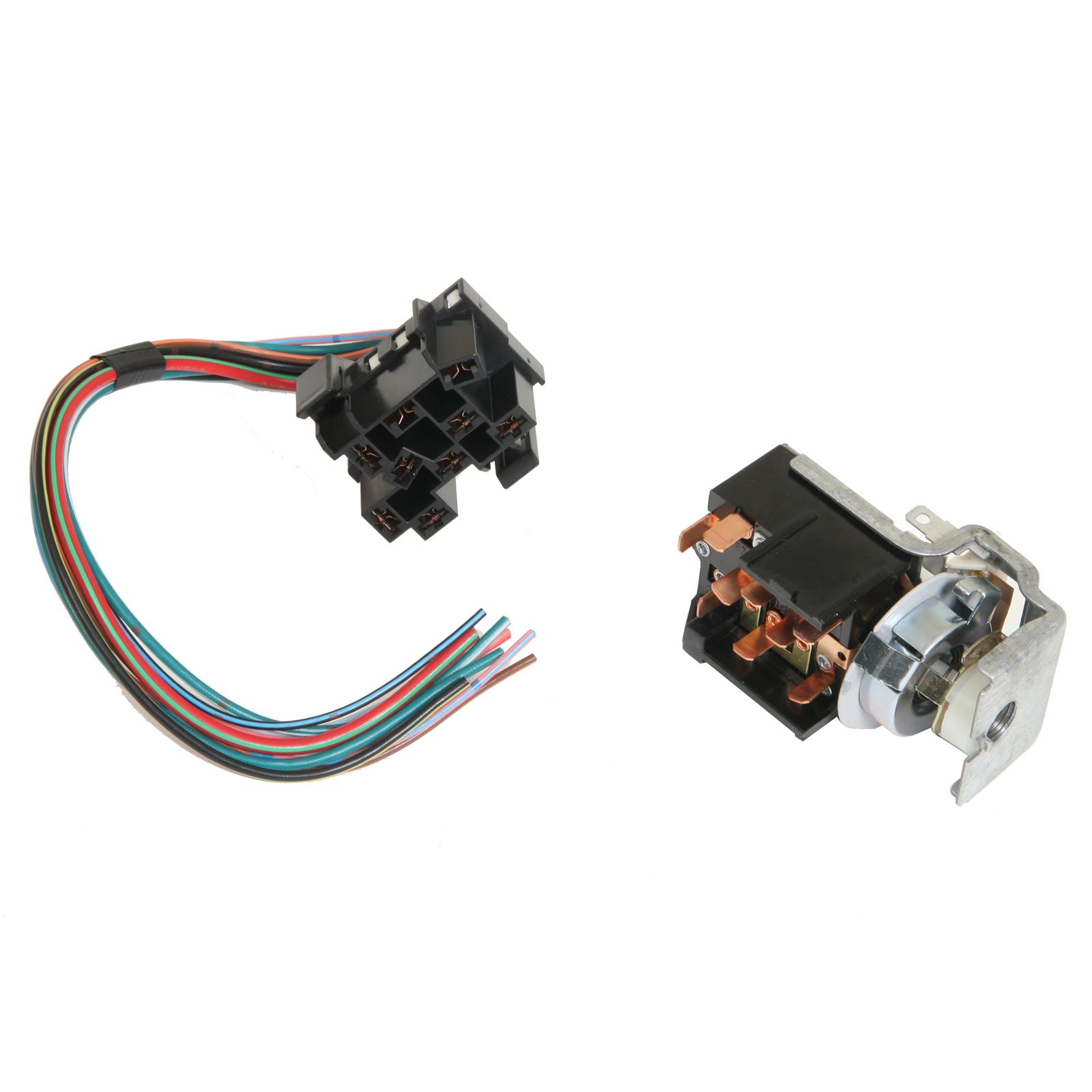
Posted by 4 months ago. Looking for help on the wiring of this dimmer switch.

Can I Hook Up A Regular Electric Drill To A Dimmer Switch
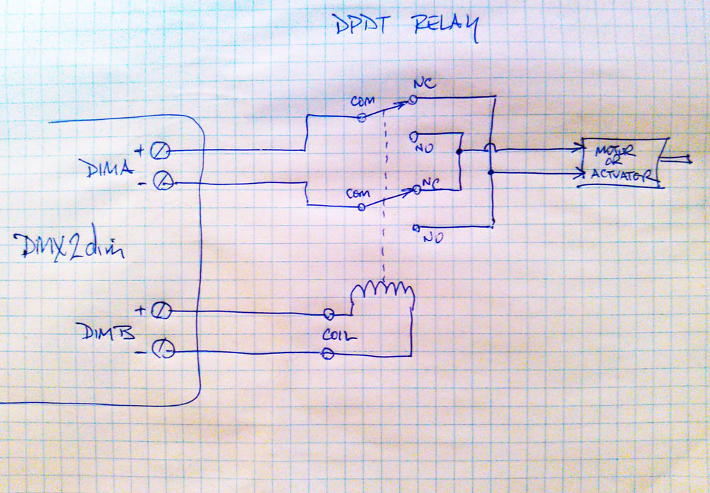
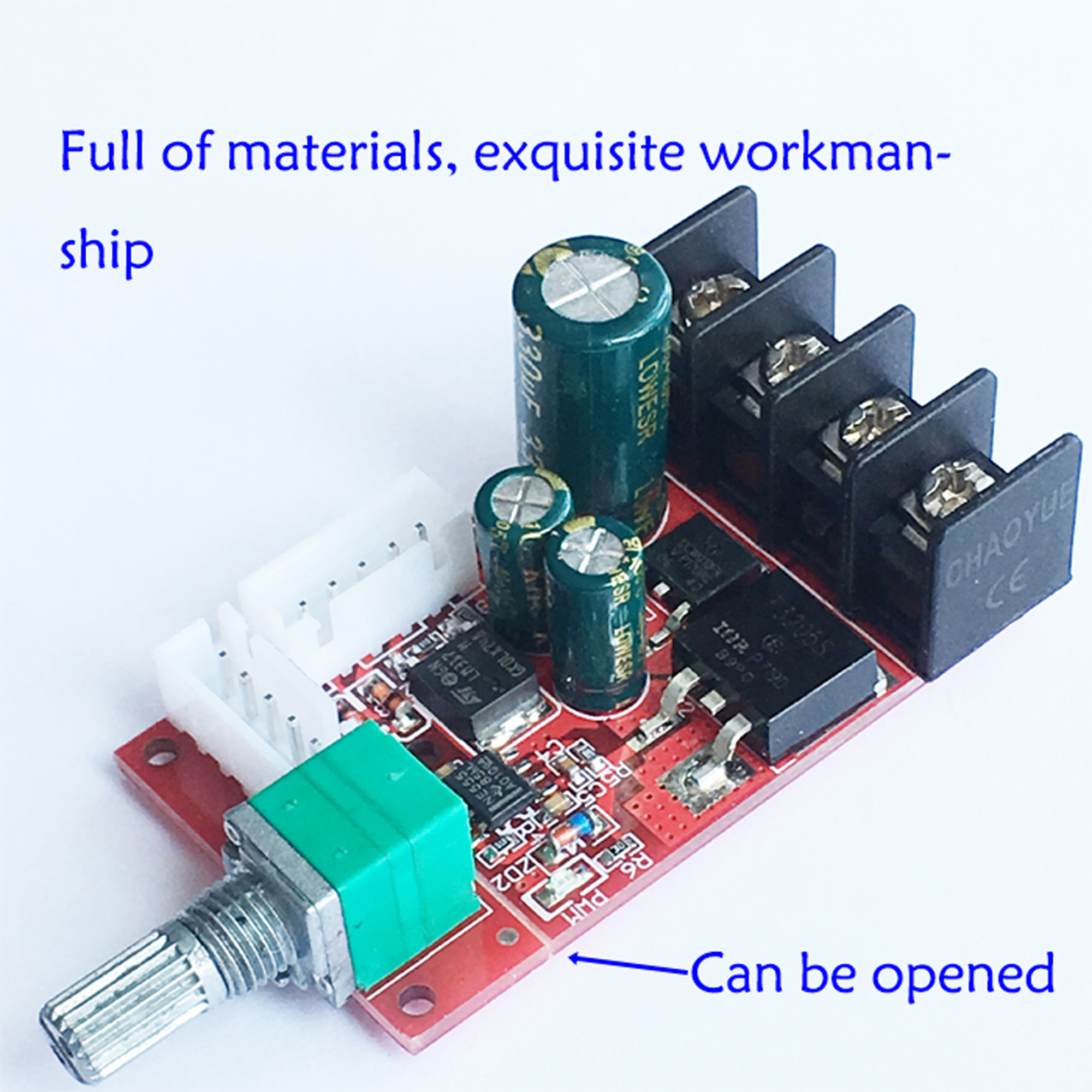
How to wire a dimmer switch to a motor. Further pairs connect the wires to the dimmer switch wrapped the joint with electrical tape. Looking for help on the wiring of this dimmer switch. Just to get the motor to. Connect the wires from the dimmer switch to the correlating wires in the wall box. Currently only one the left works. Higher amps draw might indeed be a problem.
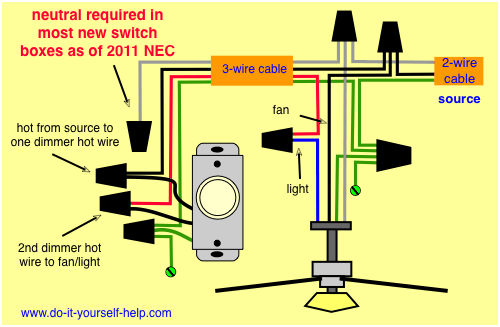
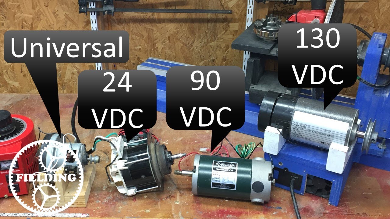
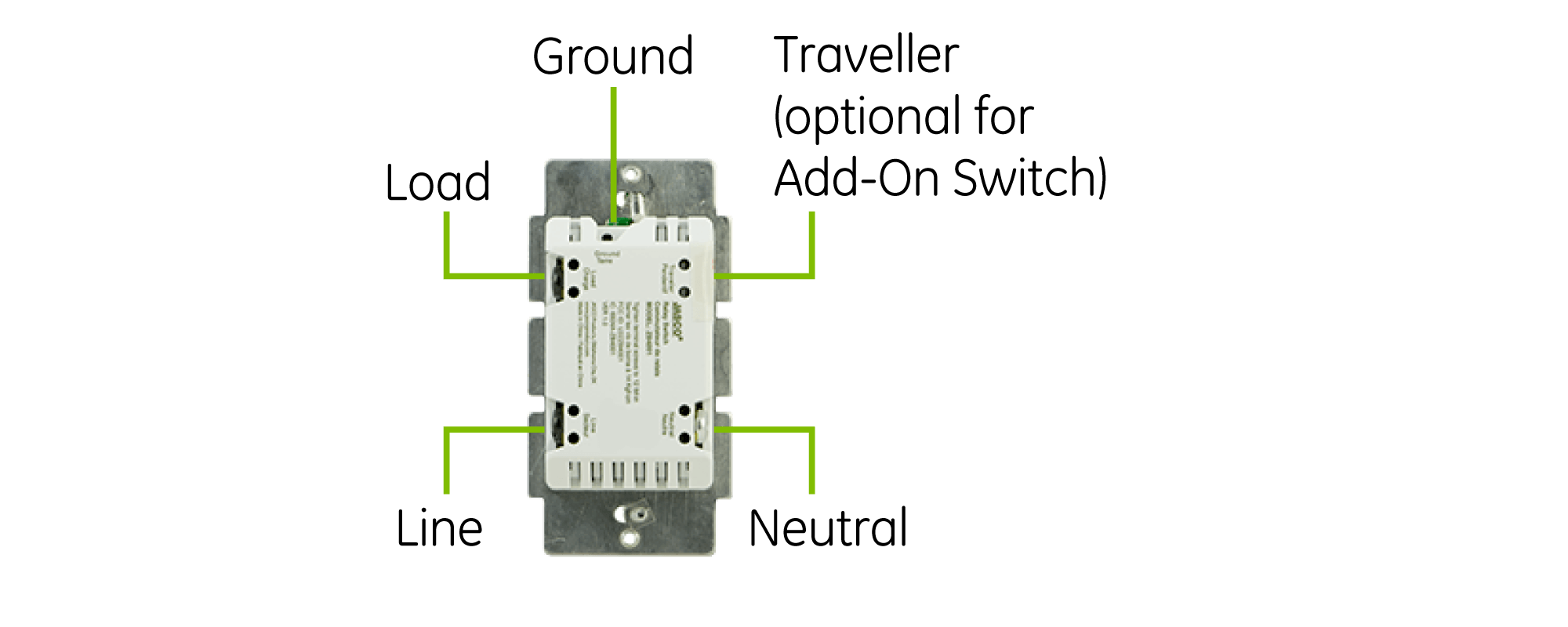
Twist the bare wire ends together and attach new wire nuts to all of the wires. In the diagram below a 2 wire nm cable supplies power from the panel to the dimmer box. C by ge customer support. Traveler wires are interchangeable on each switch. However since most ceiling fans come equipped with a variable speed fan motor using a dimmer switch to control the fan speed will damage the motor. Stack exchange network consists of 177 qa communities including stack overflow the largest most trusted online community for developers to learn share their knowledge and build their careers.
Question i bought a ge smart switch the onoff 3 wire 3 way switch. There is always a hazard that the startup of the motor has a peak current draw higher than the running power draw. You will want to use a variable speed fan switch or remote if you wish to control the fan speed. Helpful 3 unhelpful 0 report answer this question show more answers 2 q. Answered 9 months ago by ge lighting expert. Disconnect all wires from the old switch by loosening the screws and disconnecting them.
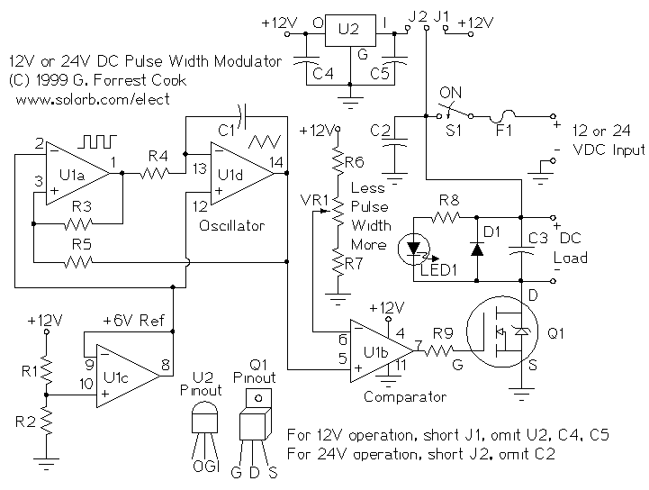
Maximum wire length from dimmer to all installed remotes cannot exceed 300 ft 90 m. Then test the dimmer switch and if that works tight fit the unit back into the wall being careful not to twist and bend wires. Dimmer switch for motor speed control. Now in the diagram above the power source is coming in from the left. A 3 wire nm connects the travelers of the dimmer to the travelers of the 3 way switch. Start with the hot wires.
Disconnect power at circuit breaker or fuse when servicing installing or removing fixture. The black line wire connects to the common terminal of the 3 way dimmer. This simple diagram below will give you a better understanding of what this circuit is accomplishing. The dimmer switches for lighting seem to provide lesser max watts for retail versions. So a lot of these switches start at full on and then you adjust downward. Currently only one the left works.
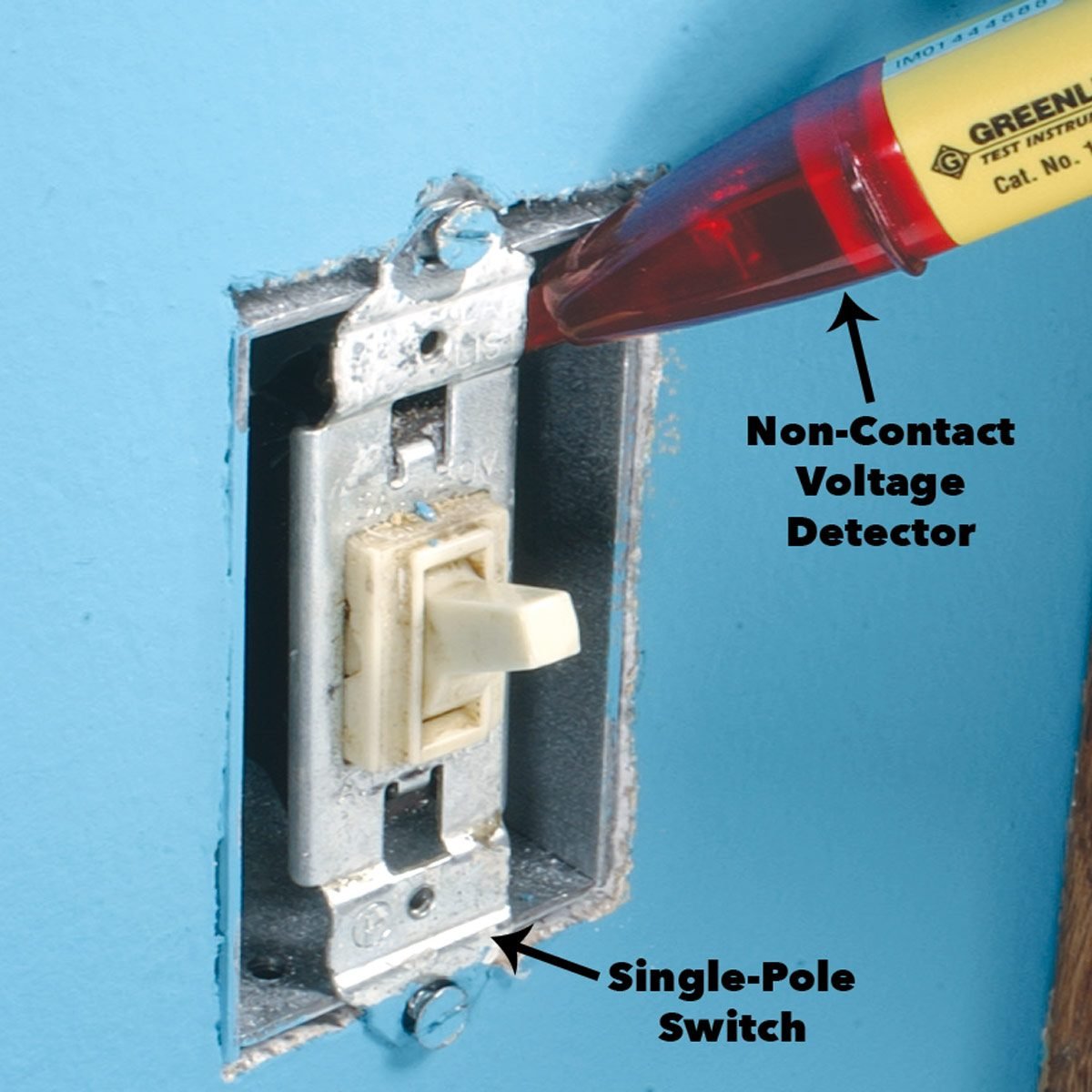
Use this device only with copper or copper clad wire. When wiring a dimmer switch circuit all we want to do is to control the black wire hot wire to turn dimbrighten the load. Log in or sign up to leave a comment.
Gallery of How To Wire A Dimmer Switch To A Motor
%2C445%2C291%2C400%2C400%2Carial%2C12%2C4%2C0%2C0%2C5_SCLZZZZZZZ_.jpg)