Wiring diagrams 11 electronic components in schematics 15 mechanical devices 16 passive devices 19 active devices 29 interpreting digital circuit schematics 56 basic digital gates 57 common digital integrated circuits 63 common digital circuit applications 65 common 555 timer circuits 70 reading datasheets 72 self check answers 79 examination 81 v contents contents. 1815mb industrial electrical wiring diagrams as pdf wiring electrical diagrams industrial as docx industrial electrical wiring diagrams as pptx industrial electrical wiring diagrams how easy reading concept can improve to be an effective person.
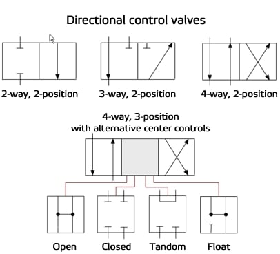
Reading Fluids Circuit Diagrams Hydraulic Amp Pneumatic Symbols
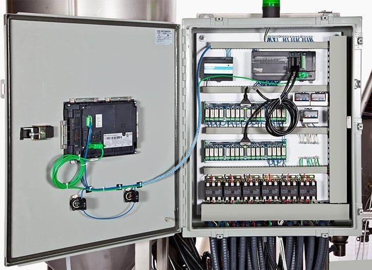
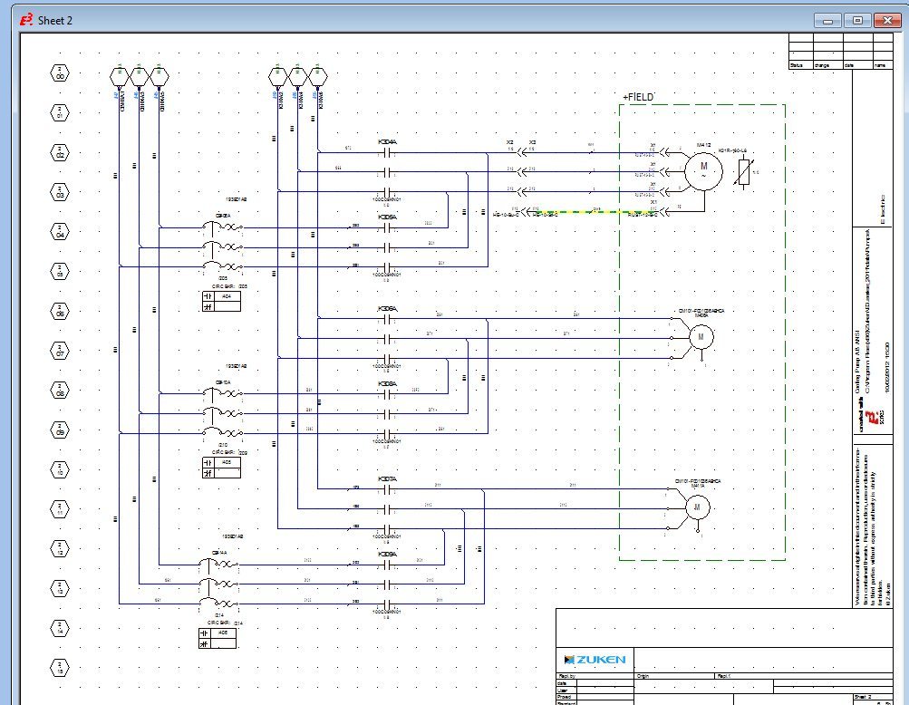
How to read industrial electrical schematics pdf. Modern industrial automation panel. The creation of such a standard acceptable to the manufacture of electrical equipment and to industrial military and. Basics 2 72 kv one line. Basics 9 416 kv pump schematic. Basics 11 mov schematic with block included basics 12 12 208 vac panel diagram. Bility of preparing a drafting standard covering electrical schematic wiring and block diagrams for use in the communications electronic electric power indus trial control telephone telegraph and allied industries a natural addition to this scope was the inclusion of military considerations through participation by re presentatives of the department of defense.
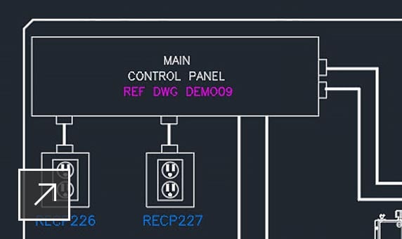
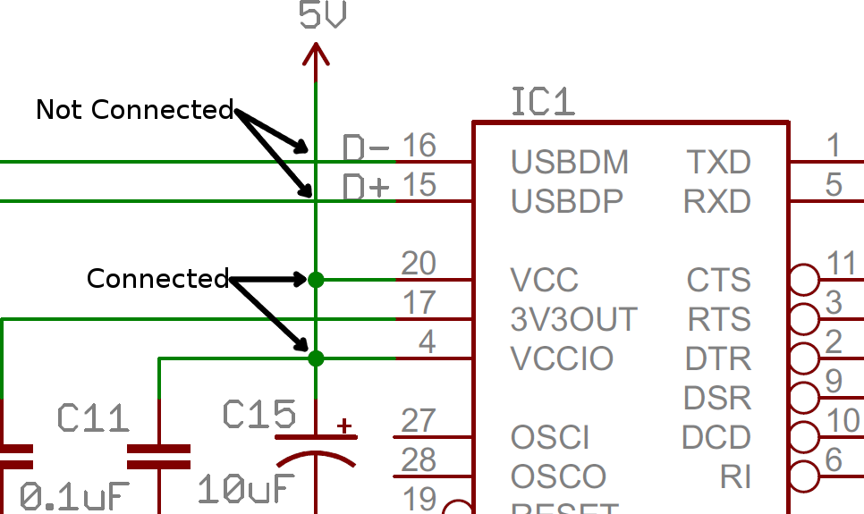
Industrial electrical wiring diagrams review is a very simple task. Basics 19 instrument loop diagram. To read electrical schematics the fundamental electrical schematic symbols should be understood. Basics 1 plant 1 line. Yet how many people can be lazy to read. In addition to the symbol each component on a schematic should have a unique name and value which further helps to identify it.
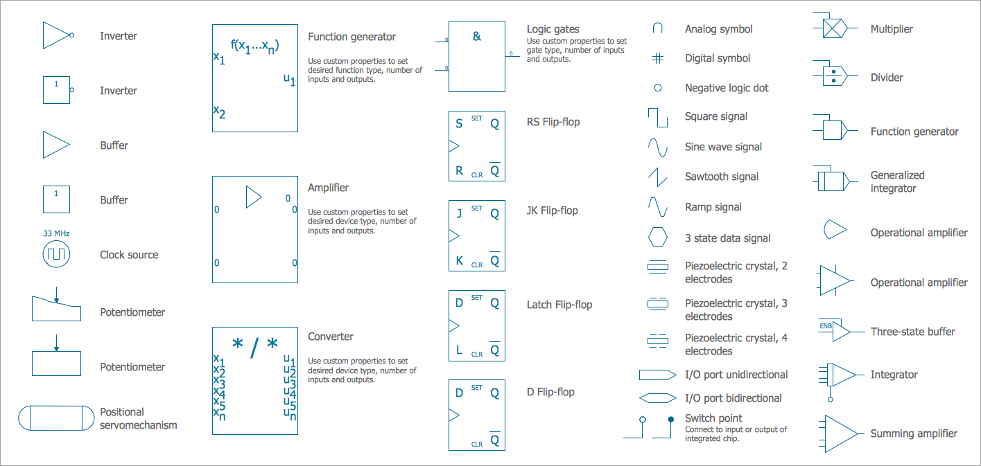
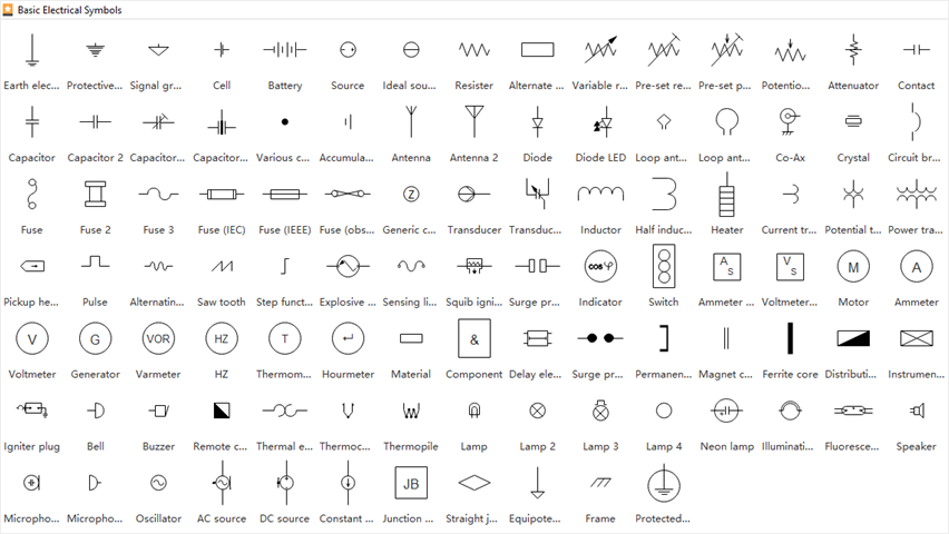
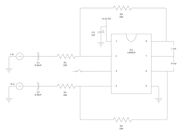
Recognizing electrical schematic symbols here are some of the standard and baisc symbols for various components for electrical schematics. Then well talk about how those symbols are connected on the schematics. Basics 10 480 v pump schematic. 1 drawings representing electronic equipment electrical and electronic technicians are often called on to install and maintain. Name designators and values one of the biggest keys to being schematic literate is being able to recognize which components are which. Basics 18 embedded conduit drawing.
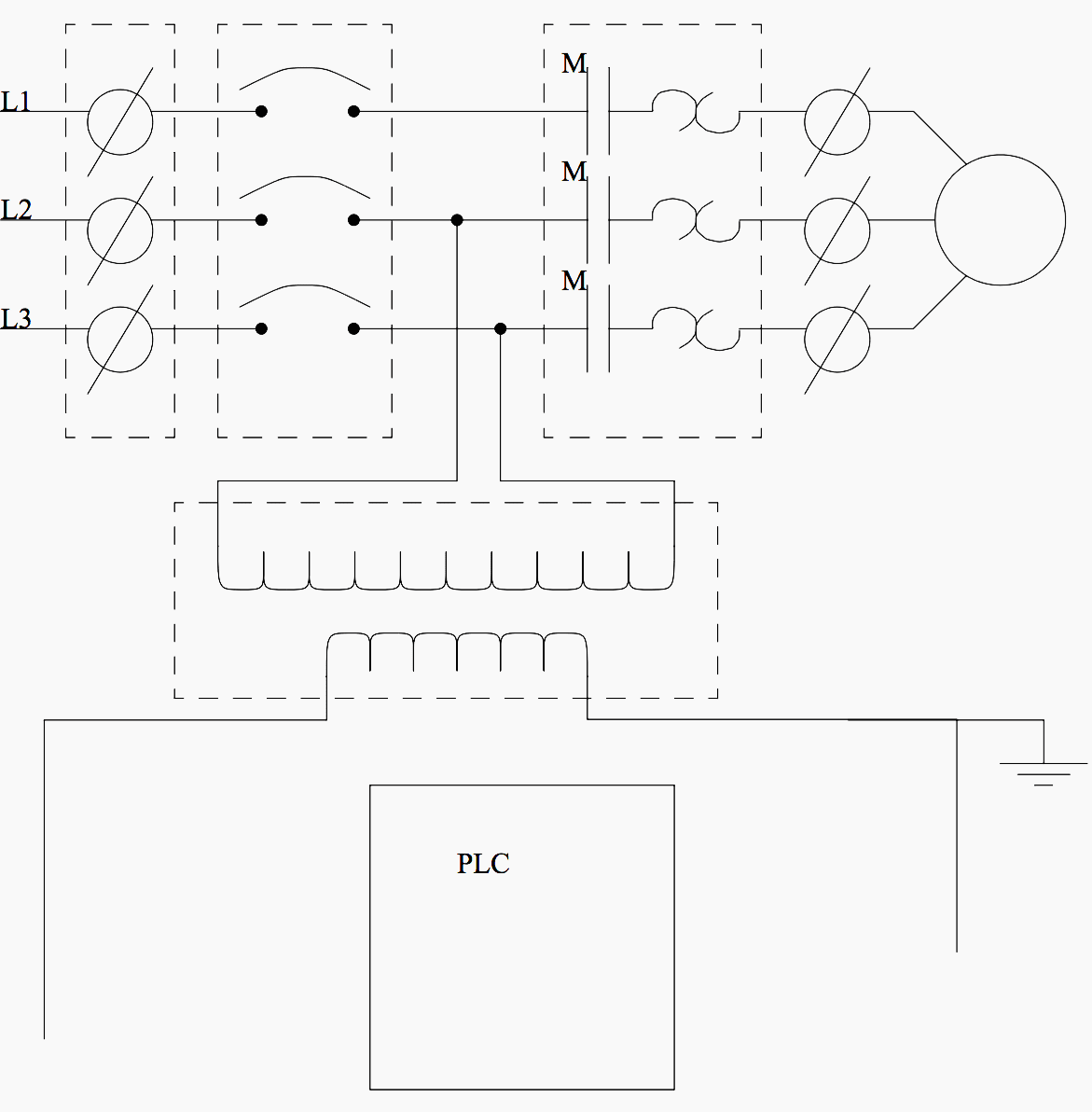
Basics 14 aov schematic with block included basics 15 wiring or connection diagram. Resistors are the fundamental components of electrical schematics. In an industrial setting a plc is not simply plugged into a wall socket. Basics 16 wiring or connection diagram. Basics 13 valve limit switch legend. If you want to droll books lots of novels tale jokes and more fictions.
1997 ford expedition eddie bauer electrical schematics 15 pdf drive search and download pdf files for free. Literate in schematic reading. Industrial electrical installation documents 15 pdf drive search and download pdf files for free. When in fact review industrial electrical wiring diagrams certainly provide. 1997 ford expedition eddie bauer electrical schematics 1997 ford expedition eddie bauer if you ally habit such a referred 1997 ford expedition eddie bauer electrical schematics books that will manage to pay for you worth get the certainly best seller from us currently from several preferred authors. In general symbols should share a fair amount in common with the real life components they model.
This article discusses the design issues in implementation that must be considered by the designer. Basic electrical design of a plc panel wiring diagrams on photo. Industrial electrical installation documents industrial electrical installation documents electrical installation standards furthermore for performance of the low voltage electrical installation work the company must hold an installation authorisation issued by esti the federal inspectorate for heavy current installations wwwestich the installation authorisation must be issued in the. The electrical design for each machine must include at least the. They prefer to invest their idle time to talk or hang out. They are usually represented by zig zag lines with two terminals extending outward.
But you can also use the. Basics 17 tray conduit layout drawing. The component symbols tell half the story but each symbol should be paired with both a name and. Electrical wiring diagrams of a plc panel.
Gallery of How To Read Industrial Electrical Schematics Pdf