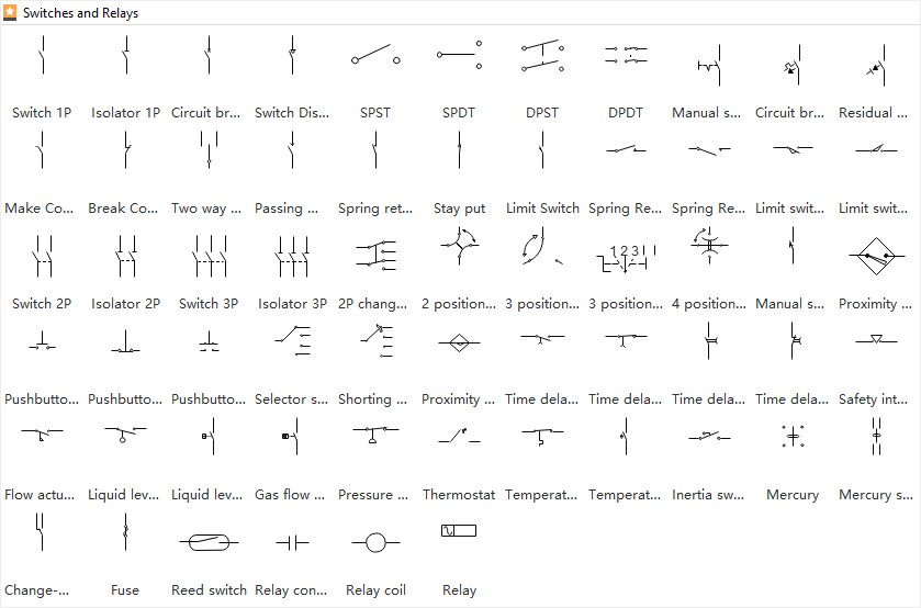
22 various categories of electrical drawings 31 23 planning your drawing 33 24 title block in a drawing and what it should contain 40 25 legend block 43 26 bill of materials block 44 27 drawing notes block 44 28 revision history revision numbering and use of revision marks 45 29 summary 47 3 symbols used in electro technology and governing standards 49 31 types of drawings that need symbols 49 32 symbols as per electro technology standards 52 33 use of non standard symbols 70 34. Recognizing electrical schematic symbols here are some of the standard and baisc symbols for various components for electrical schematics.
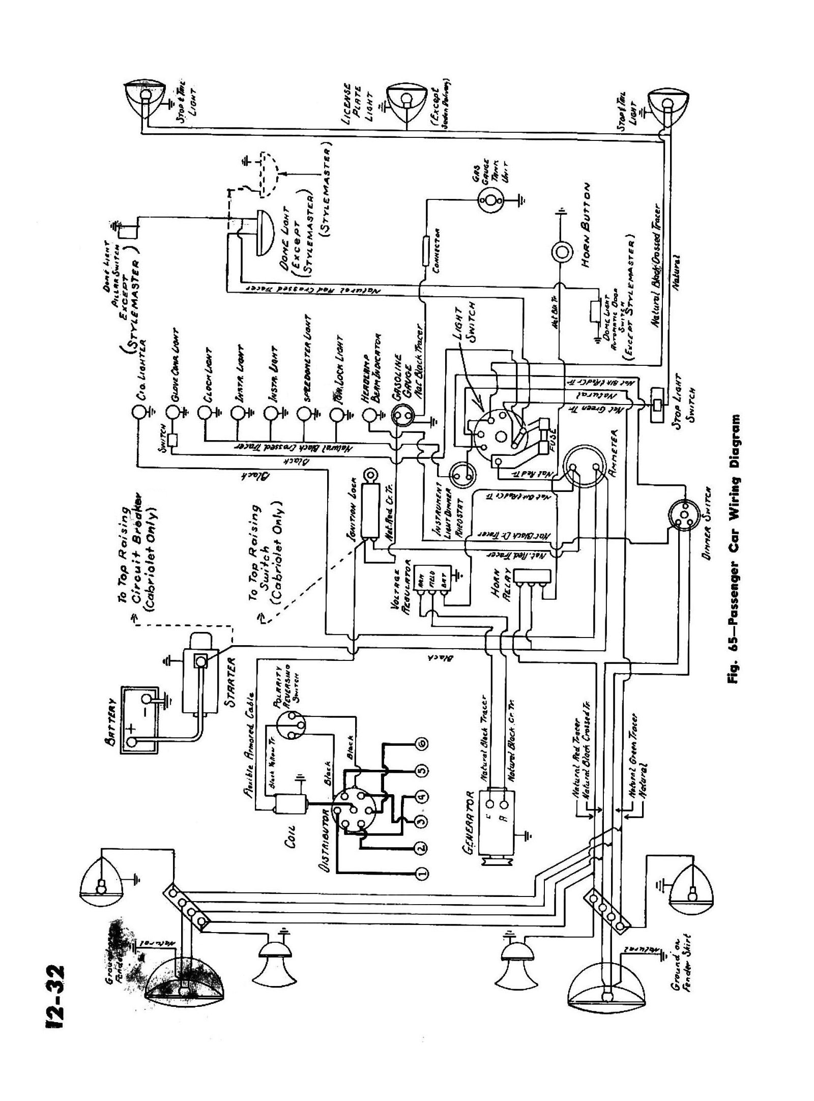
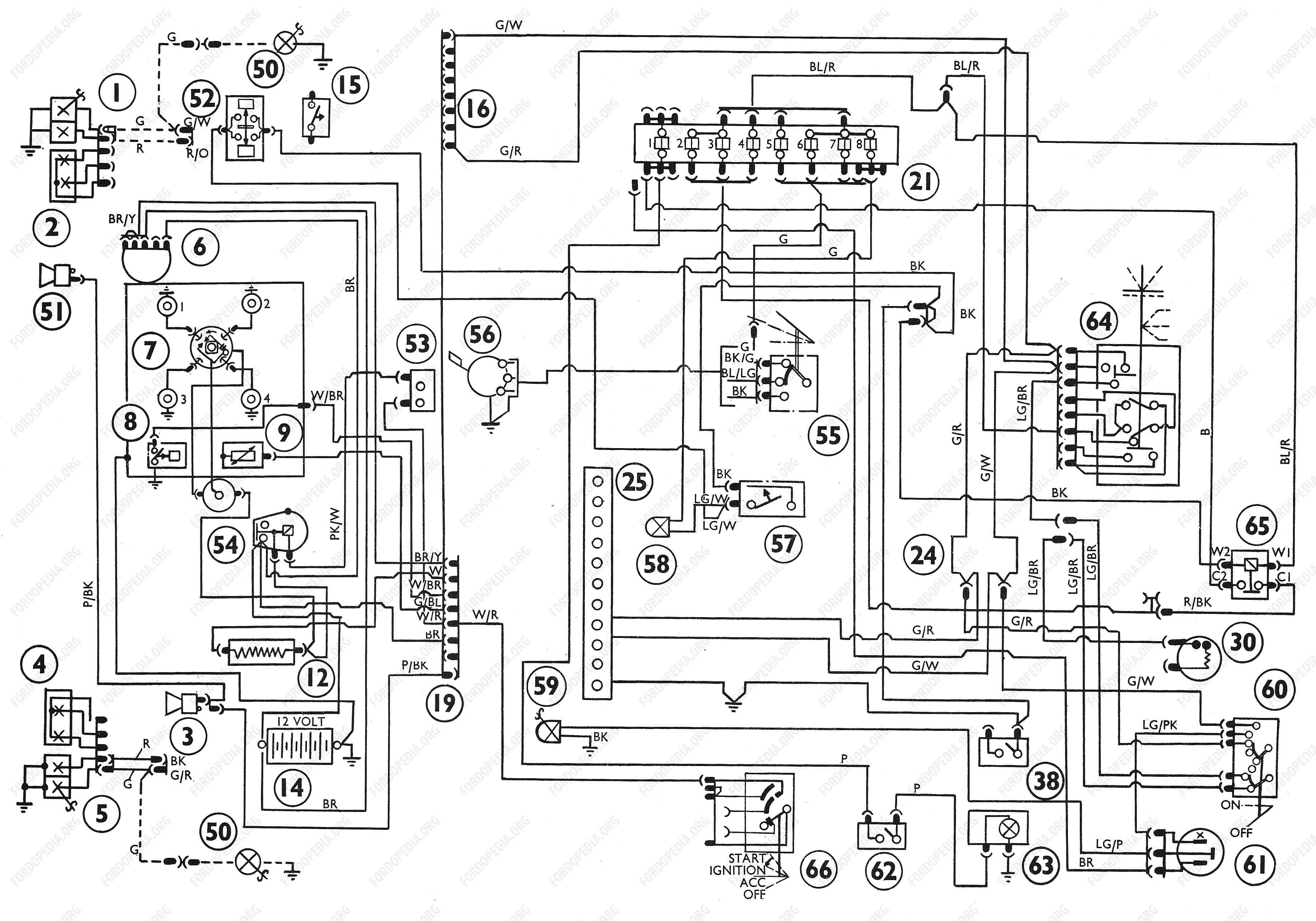
Chevy Wiring Diagrams
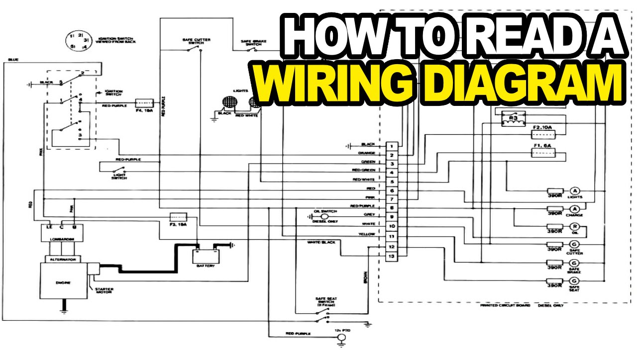
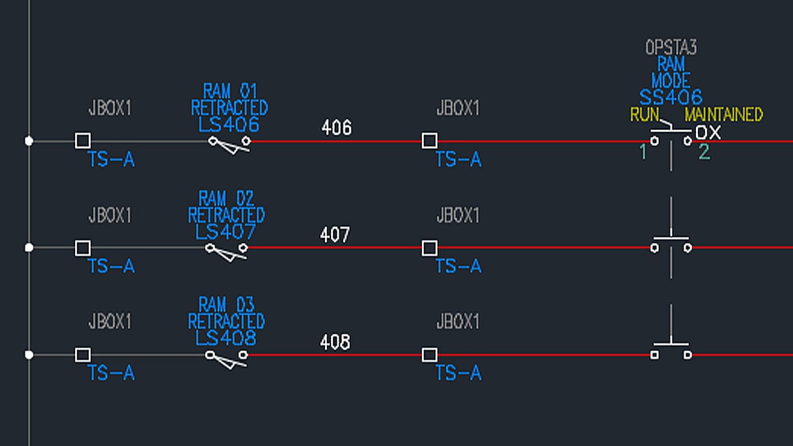
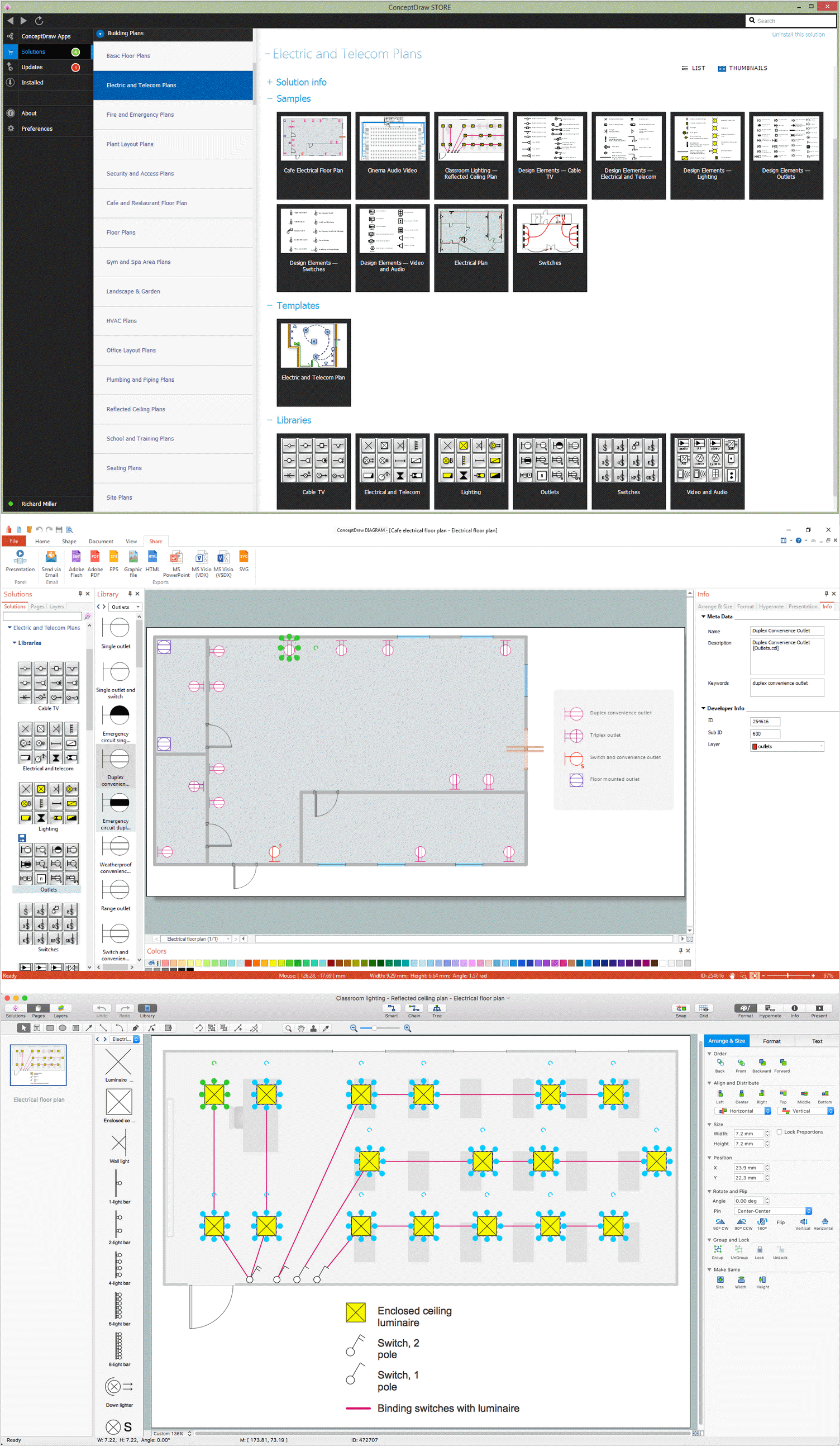
How to read electrical drawings pdf. Free download free download free download. Accordingly some specifications may not be applicable for individual vehicles. With rare exceptions schematics should be read left to right and top to bottom. A 2 how to read the wiring diagrams composition and contents of wiring diagrams composition and contents of wiring diagrams 1 this manual consists of wiring harness diagrams installation locations of individual parts circuits diagrams and index. Basics 13 valve limit switch legend. A diagram that uses lines to represent the wires and symbols to represent components.
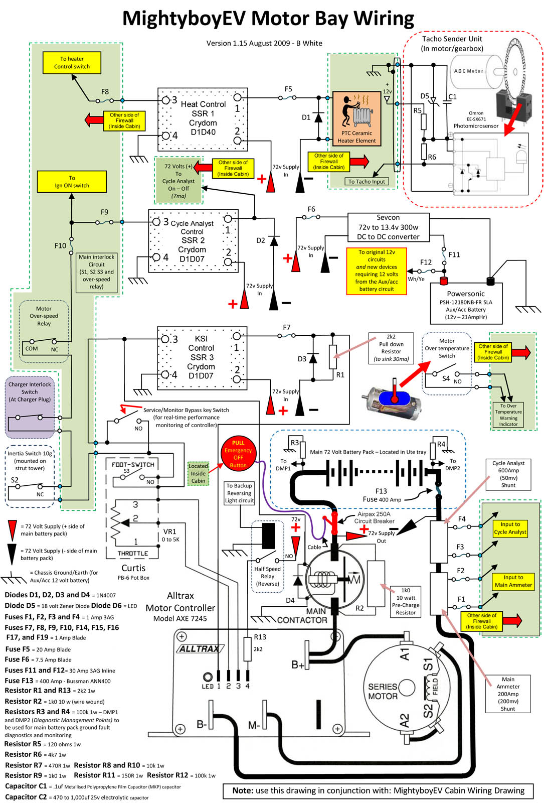
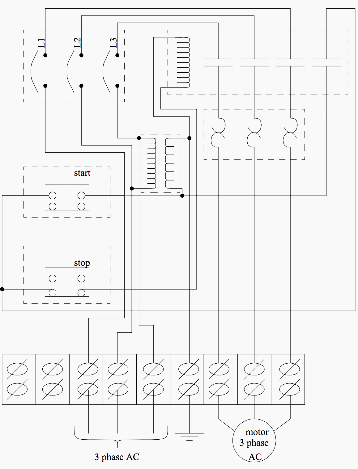
Basics 17 tray conduit layout drawing. Basics 10 480 v pump schematic. Electrical and electronics diagrams usas y1415 1966 usa standard approved includes the following. A diagram that represents the elements of a system using abstract graphic drawings or realistic pictures. The signal generated or used by the circuit will flow in this direction. 2 in each section all specifications are listed including optional specifications.
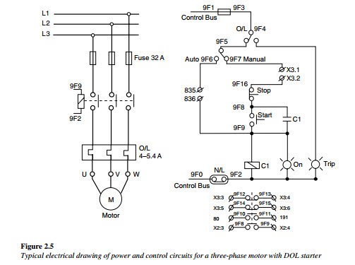
Section basic contents wiring harness configuration diagrams connector. The user can follow the same path that the signal uses to. Basics 14 aov schematic with block included basics 15 wiring or connection diagram. Basics 8 aov elementary block diagram. Basics 16 wiring or connection diagram. Control wiring schematic and single line diagrams.
Basics 6 72 kv 3 line diagram. To be able to read electrical as well as other types of drawings one must become familiar with the meaning of symbols lines and abbreviations used on the drawings and learn how to interpret the message conveyed by the drawings. To the final design. Basics 18 embedded. Electrician circuit drawings and wiring diagrams youth explore trades skills 3 pictorial diagram. Learn reading pattern read schematics in the pattern that you would read the text.
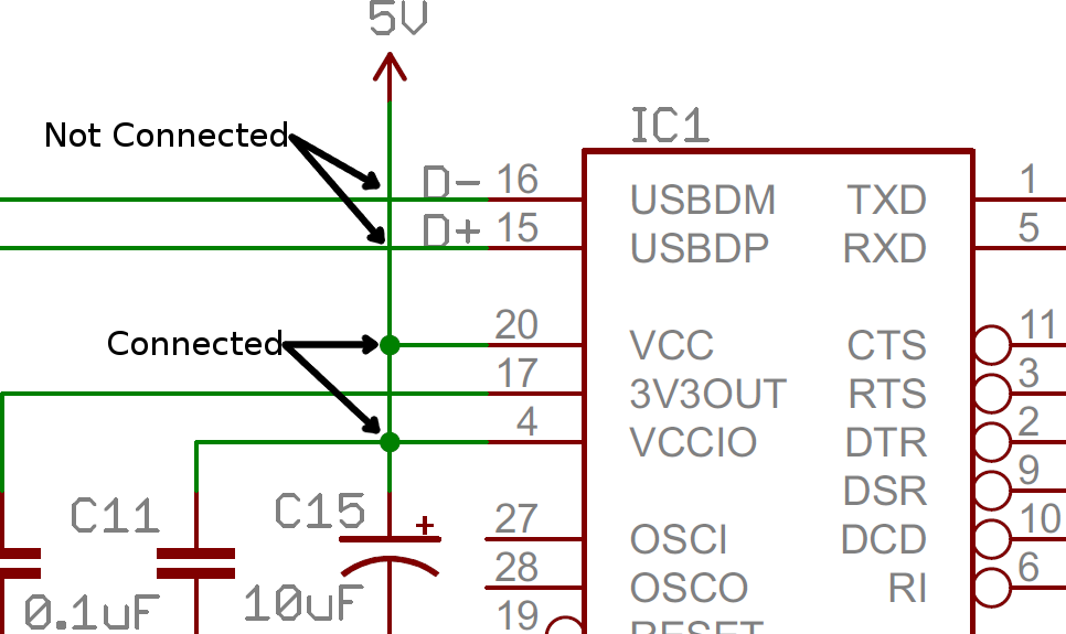
A drawing of an electrical or electronic circuit is known as a circuit diagram but can also be called a schematic diagram or just schematic. Circuit or schematic diagrams consist of symbols representing physical components and lines representing wires or electrical. To read electrical schematics the fundamental electrical schematic symbols should be understood. Schedules notes and large scale details on construction drawings. Resistors are the fundamental components of electrical schematics. Should be included in a symbols list and attached.
How to read a electrical drawing 1. Learn to read electrical and electronic circuit diagrams or schematics. Familiarize with standardized electrical symbols. Basics 11 mov schematic with block included basics 12 12 208 vac panel diagram. 15 1 scope 15 2 definitions 15 3 general infonnation 15 4 single line diagrams general 15 5 single line diagrams electronics and communications 15 6 single line diagrams power switchgear and industrial control 15 7 schematic diagrams general 15 8 schematic diagrams electronics and communication 15 9 schematic diagrams power switchgear and industrial control proposed usa standard. Occasionally the need may arise for a symbol that has not been developed.
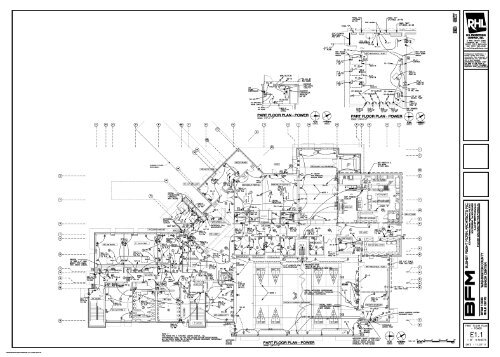
Electrical calculations single line diagrams and lighting system energy requirements the number of electrical sheets required for a proj ect varies based on the amount of required infor mation that each project requires and how much of that information can fit on one page and still pro vide for a clear concise understandable set of prints. Feel free to export print and share your diagrams. They are usually represented by zig zag lines with two terminals extending outward. Basics 9 416 kv pump schematic. Then well talk about how those symbols are connected on the schematics. Power riser diagrams to show the service entrance and panelboard components.
But you can also use the. Basics 7 416 kv 3 line diagram.
Gallery of How To Read Electrical Drawings Pdf