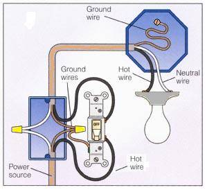
Alarm or limit warning hookup. A wiring diagram is a simplified standard photographic representation of an electric circuit.
Forberg Scientific Inc How To Install 70 Series Go Switch
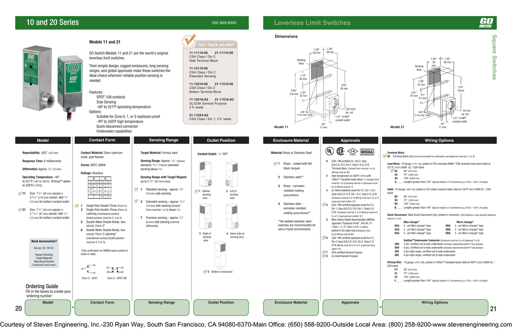
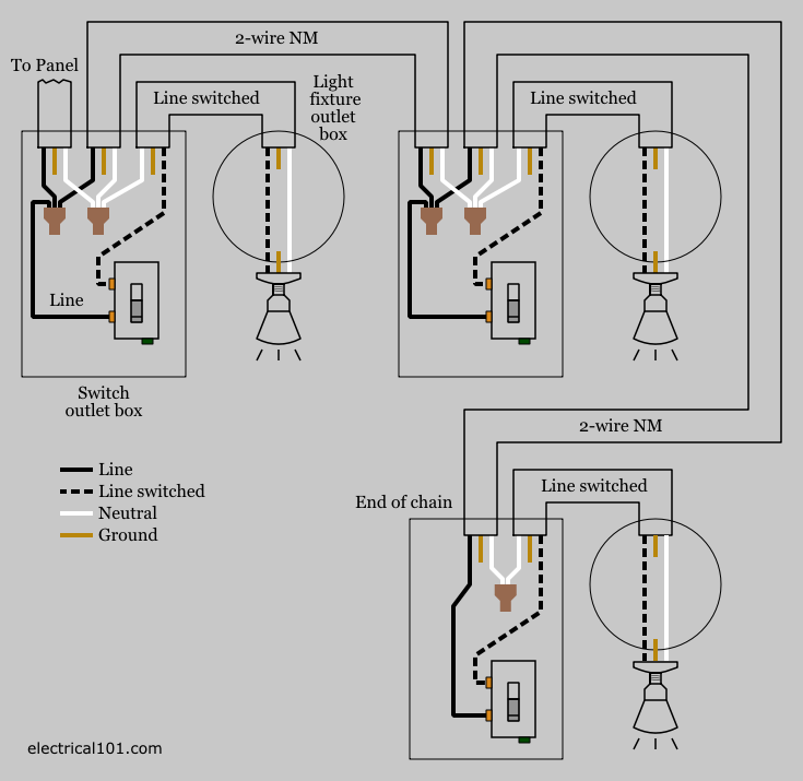
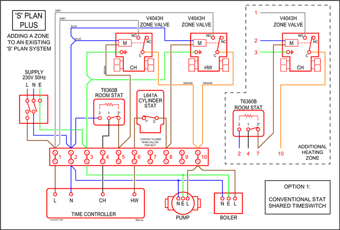
Go switch wiring diagram. As the all in one proximity sensor and limit switch go switches provide accurate final control to support quality and efficiency in a variety of industries. To describe go switch leverless limit switches. By combining the best of the two technologies go switch enjoys a double advan. Three wire cable runs between the switches and the outlet. Or these terminals can be ignored for non backlit switch banks. An example of three way switch wiring with the line and load in the same 4 square electrical box.
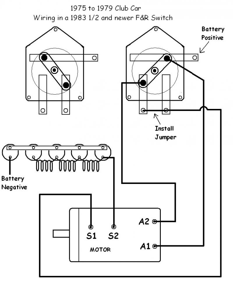
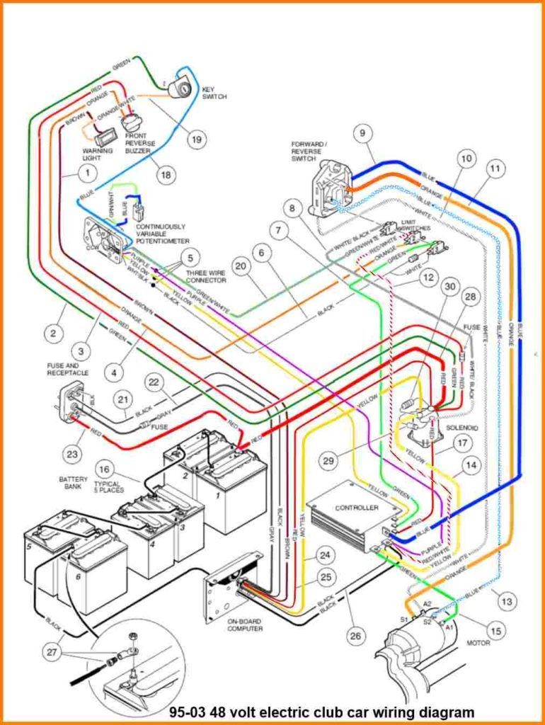
Whether you have power coming in through the switch or from the lights these switch wiring diagrams will show you the light. Go switch products are engineered to meet tough applications while offering high reliability installation flexibility and dependability in all environments. Wiring a 2 way switch is about as simple as it gets when it comes to basic house wiring. Light switch wiring diagram single pole this light switch wiring diagram page will help you to master one of the most basic do it yourself projects around your house. Variety of ezgo forward reverse switch wiring diagram. You would just continue from one 3 way switch box with the 143 three conductor cable two colored traveler wires a white neutral and a bare or green ground wire in.
3 way switch wiring diagram with line and load in the same switch box. The white wire between switches is not being used as a neutral. It shows the components of the circuit as streamlined shapes as well as the power and signal connections between the tools. When wiring this switch you can choose if youd like to illuminate it because of the independent lamp attached to terminals 8 and 7. The wiring diagram to the right will show how to wire and power this 12v 20amp on off on 3 way carling contura rocker switch. You see go switches have a unique hybrid design that combines the advantages of mechanical limit switches with the advantages of inductive proximity sensors and leaves their drawbacks behind.
This circuit is wired the same way as the 3 way lights at this link. The source is at the sw1 where the hot is connected to. Below are some four way switch wiring diagrams. In this diagram two 3 way switches control a wall receptacle outlet that may be used to control a lamp from two entrances to a room. The white wire must be re identified as a hot wire at each switch location. In some countries the four way is called an intermediate switch.
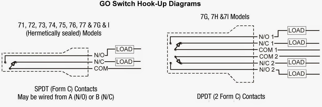
Go switch wiring diagrams ex ia iic t6 ga 40 oc to 50c ex ia iiic t85c da baseefa 12atex0187x bas 0518 ii 1 gd 40oc to 100oc ex ia iiic t135c da baseefa 12atex0187xterminal block wiring for flameproof and increased safety iecex bas 120106x 0518 ii 1 gd marking tm form a normally open typ. 3 way switched outlet wiring. First of all we need to go over a little terminology so you know exactly what is being discussed. Go to my switch terminology page where i discuss the terms used for the different types of home electrical switches.
Gallery of Go Switch Wiring Diagram