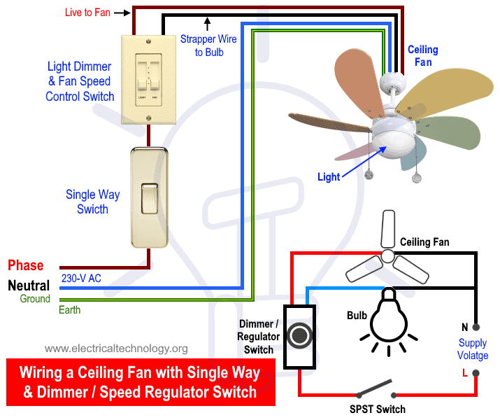
Assortment of wiring diagram 3 way switch ceiling fan and light. This wiring diagram illustrates the connections for a ceiling fan and light with two switches a speed controller for the fan and a dimmer for the lights.
24517 Hampton Bay Ceiling Fan Light Wiring Diagram 3 Way
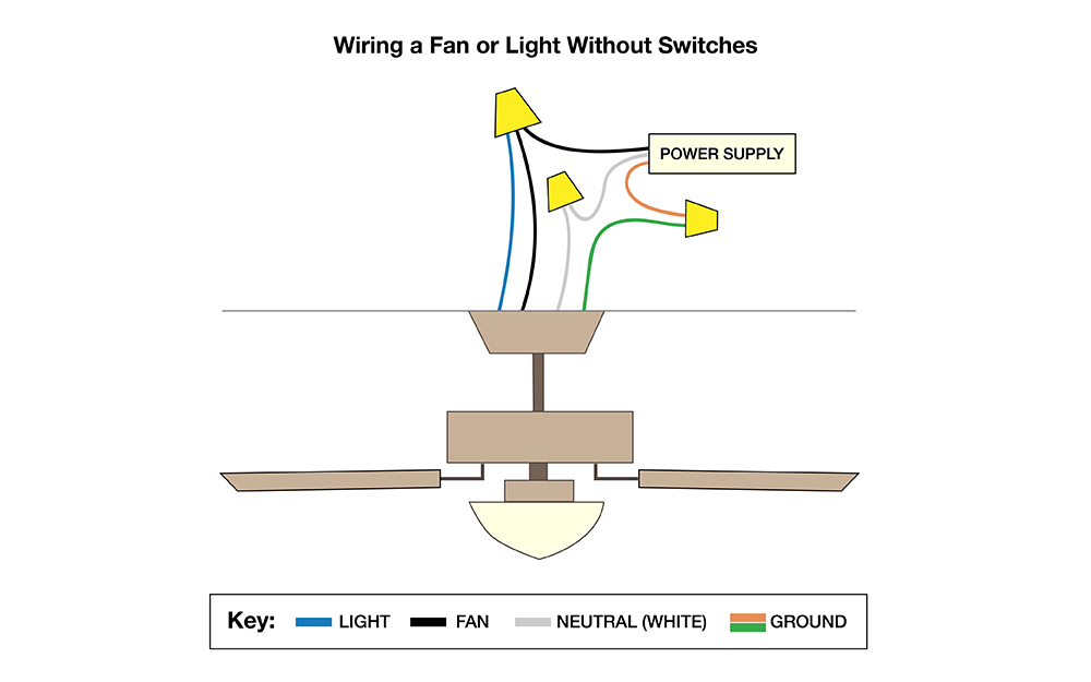
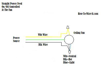
Fan and light switch wiring diagram. From the switches 3 wire cable runs to the ceiling outlet box. The fan control switch usually connects to the black wire and the light kit switch to the red wire of the 3 way cable. Red wire is sometimes included and acts as a conductor to carry power to the light kit. Green wire is for the ground. A wiring diagram is a streamlined conventional photographic depiction of an electrical circuit. Black wire is for the fan.
Switch hots and line neutral will connect to a 3 wire cable that travels to the fanlight outlet box in the ceiling. Electrical 4 way switch wiring diagram. If you had a red wire coming from your ceiling it is hooked up to your wall switch. Wiring diagram for ceiling fan with light switch. White wire is neutral. Wiring diagram for ceiling fan.
Ceiling fan and light switch wiring diagram. Switched lines and neutral connect to a 3 wire cable that travels to the lightfan outlet box in the ceiling. Blue wire is for the light if light is included with the fan. It shows the elements of the circuit as streamlined forms and also the power and also signal connections in between the devices. 21 posts related to hunter 4 wire ceiling fan switch wiring diagram. Ceiling fan wiring diagram.
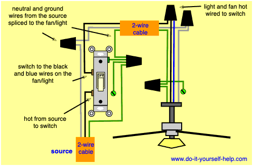
Ceiling fan switch wiring diagram 2 line voltage enters the switch outlet box and the line wire connects to each switch. 5 wire ceiling fan switch wiring diagram. Hunter ceiling fan wiring diagram switch. The source is at the switches and the input of each is spliced to the black source wire with a wire nut. The line voltage enters the switch outlet box and the hot wire will connect to every switch.
Gallery of Fan And Light Switch Wiring Diagram