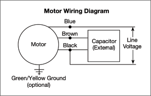
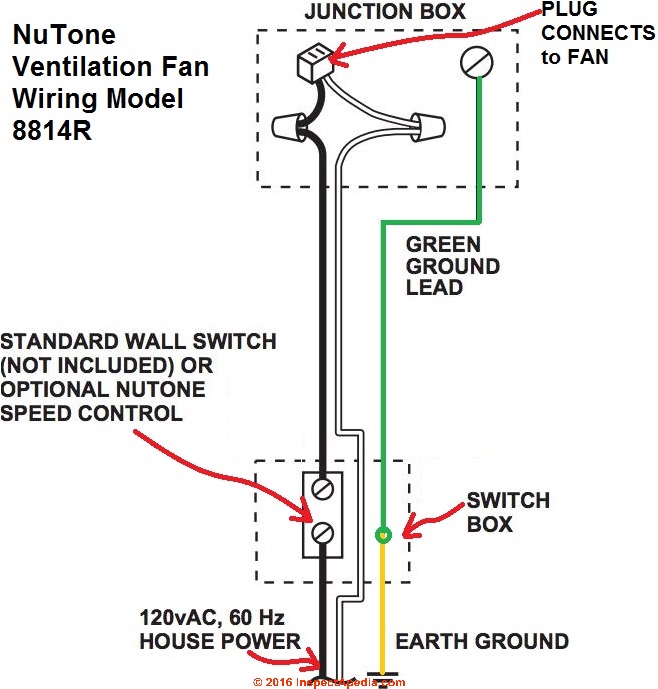
How to connect the fan wire easy to understand fan coil connector 5 wire condenser fan motor wiring diagram simplest. Variety of century electric motor wiring diagram.
Wiring Exhaust Fan Capacitor For Exhaust Fan Motor Wiring
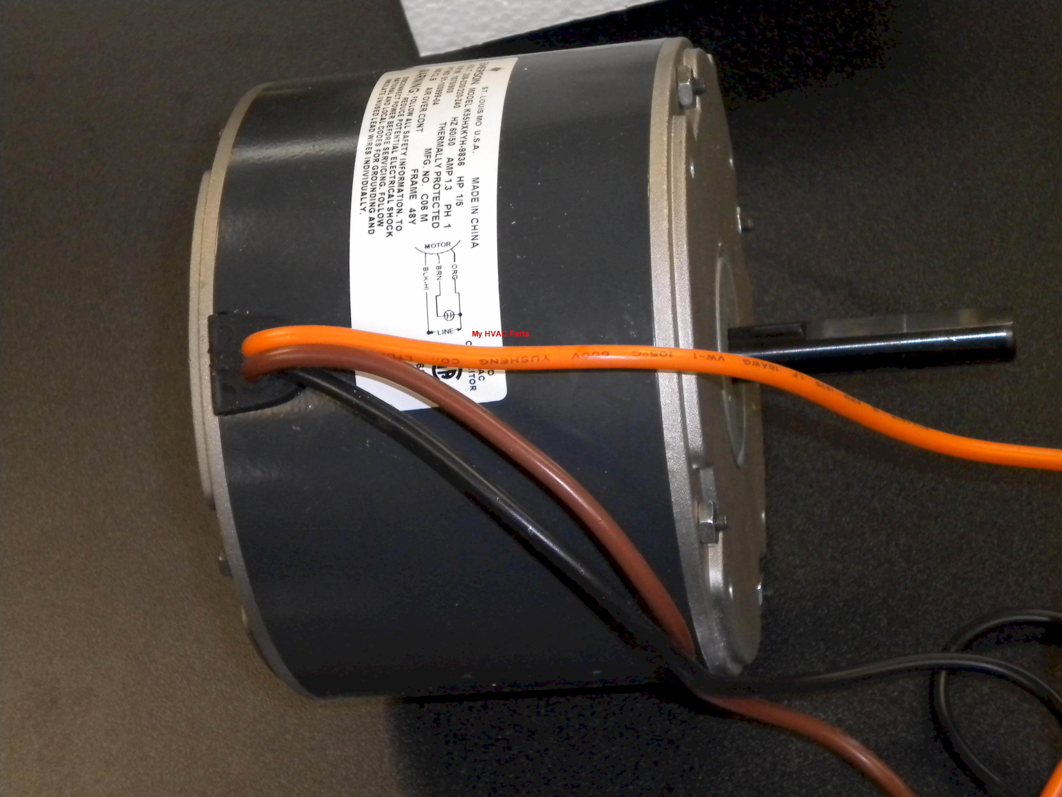
Electric fan motor wiring diagram. Finally this guide is intended to be used as a general overview of common condenser unit wiring schematics. We realize it from google search engine records such as adwords or google trends. There are 6 wires. Variety of marathon electric motor wiring diagram. We strongly recommend referring back to your units manual for proper wiring instructions. Electric fan motor wiring diagrams is one of grown topic at this time.
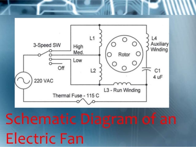
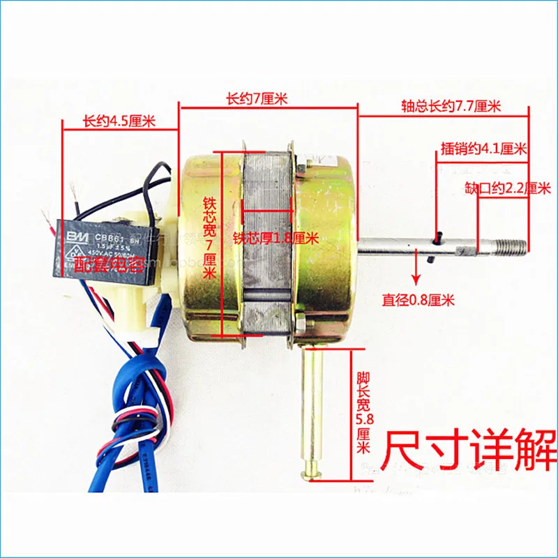
3ø wiring diagrams 1ø wiring diagrams diagram er9 m 3 1 5 9 3 7 11 low speed high speed u1 v1 w1 w2 u2 v2 tk tk thermal overloads two speed stardelta motor switch m 3 0 10v 20v 415v ac 4 20ma outp uts diagram ic2 m 1 240v ac 0 10v outp ut diagram ic3 m 1 0 10v 4 20ma 240v ac outp uts these diagrams are current at the time of publication. It reveals the parts of the circuit as streamlined shapes and the power and also signal connections between the tools. Most stand alone adjustable thermostats ie. 85 black wire. 86 graywhite wire goes to the ignition switch. The electric motor is a bm 122 decomin brand 3 speed motor.
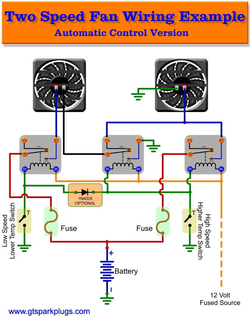
87 red wire connects to the positive wire on the electric fan. For a visual picture of typical wiring configurations reference the following guide. 3 speed ac fan running capacitor. Hvac condenser fan motor wiring diagram. In order to bring beneficial advice to our audience we have tried to obtain the nearest relevance image about electric fan motor wiring diagrams. Alfred electronic fan.
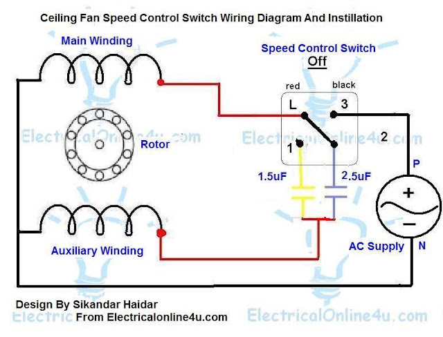
Something was wrong with the solid state circuitry everything worked but the motor but a quick test of the motor indicated it does work. The motor has a 4mu 250volt capacitor. Page 2 standard relay pins 30. Suggested electric fan wiring diagrams suggested primary cooling fan single speed onoff using 12 volt switching devices only for primary activation note. A wiring diagram is a simplified standard pictorial representation of an electrical circuit. A wiring diagram is a streamlined traditional photographic depiction of an electric circuit.
Some condenser fan motors wire to a circuit board while others use proprietary plugs for their connectors. This fan has an oscillating grill with independent sync motor and timer circuit. Relays shown in these diagrams can provide options for useful features such as an ac override on andor manual override on. 30 other red wire needs constant 12 volt power from the battery. Hayden flex a lite or perma cool brands can provide a 12 volt output when activated. Constant 12v unswitched 85.
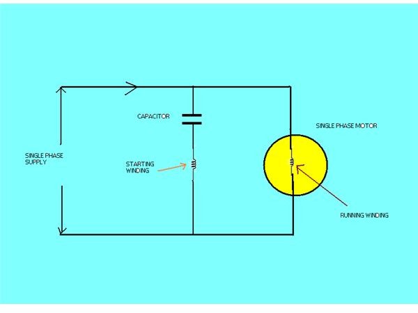
The motor uses a start and run capacitor. It has a 3 speed fan motor. It reveals the components of the circuit as simplified forms and also the power and signal connections in between the tools. I decided to.
Gallery of Electric Fan Motor Wiring Diagram