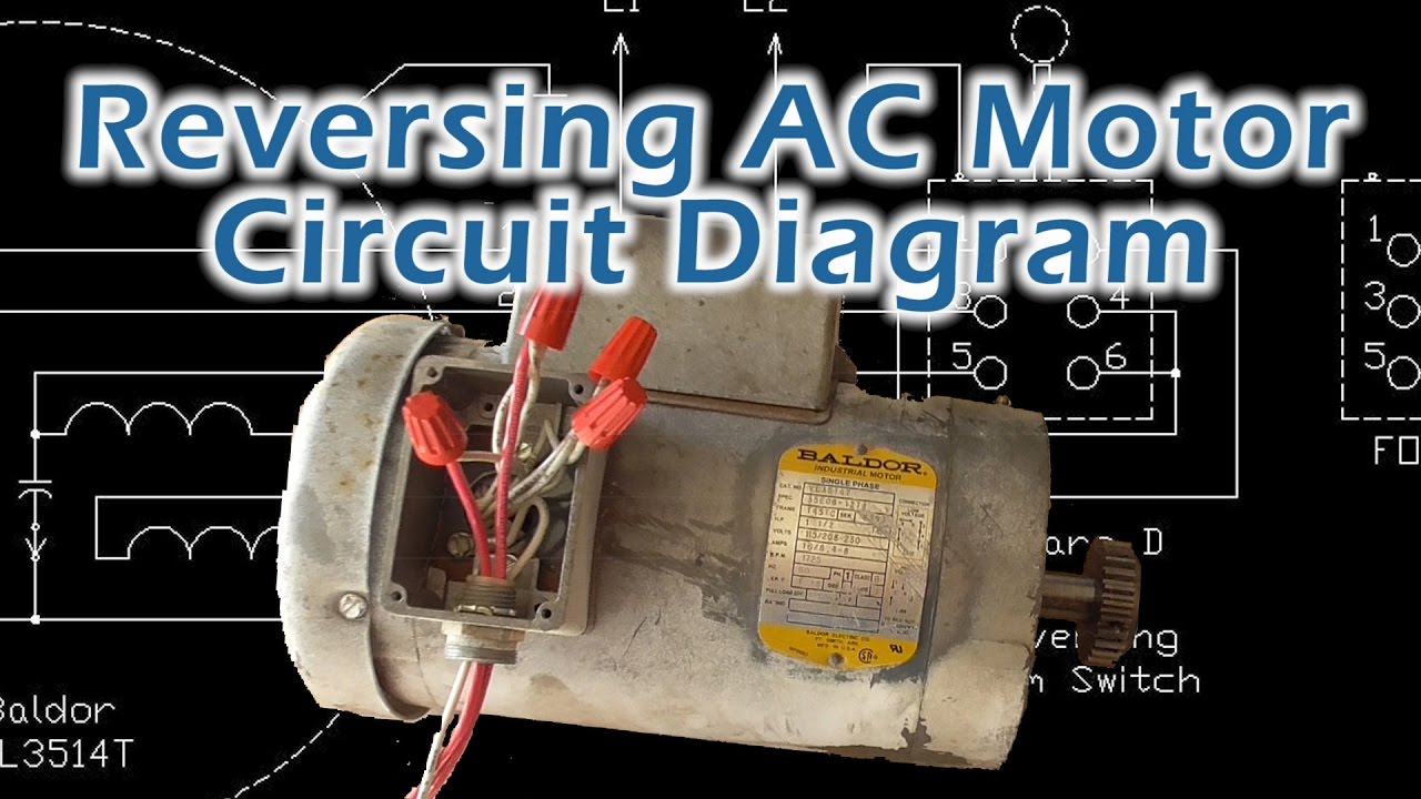
Also explain the operation of this motor control circuit. 4 wire reversible psc motor.
Ac Motors And Generators
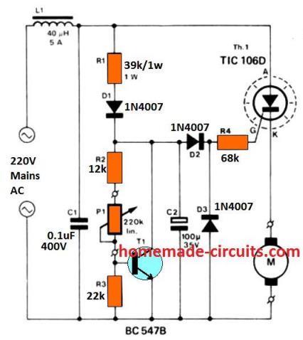
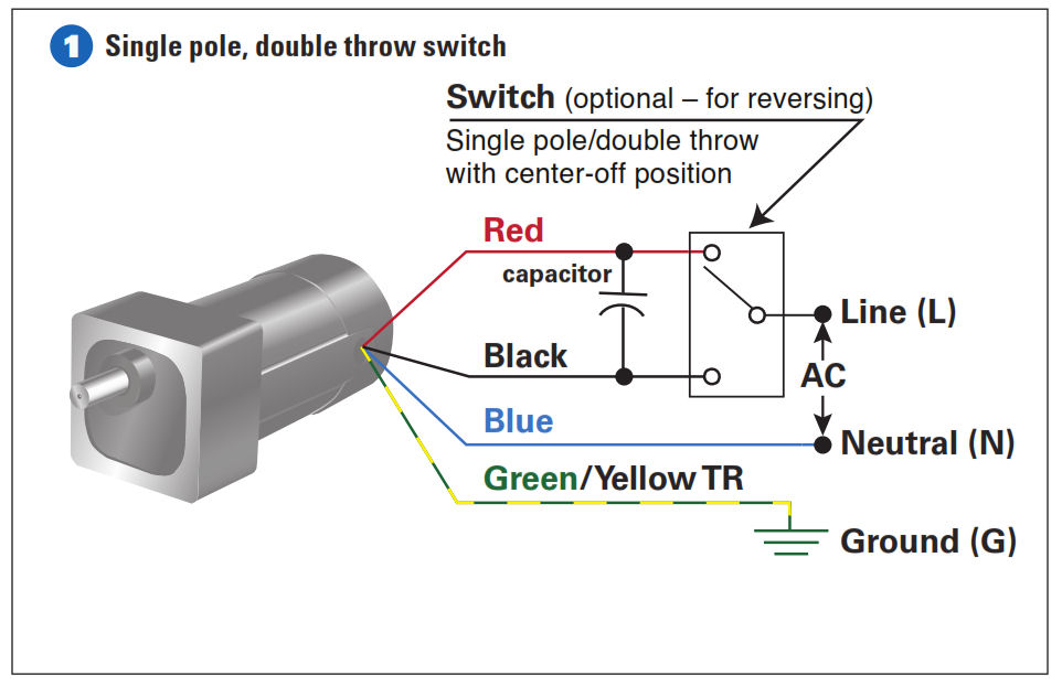
Diagram of ac motor. Ac80 ac90 ac100 single phase motors. 3 wire reversible psc motor. The theoretical speed of the rotor in an induction motor depends on the frequency of the ac supply and the number of coils that make up the stator and with no load on the motor comes close to the speed of the rotating magnetic field. The main source of the ac motor is current coming from the three phase or the single phase supply mains. The setting of p1 determines the phase of the trigger pulse that fires the triac. In practice the.
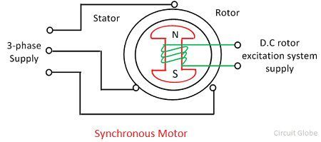
Wiring diagram includes both examples and step by step guidelines that would permit you to definitely truly construct your project. Ac motor diagrams basic stator and rotor operation. An ac motor uses alternating current in other words the direction of current flow changes periodically. Dc servo motors are separately excited dc motor or permanent magnet dc motors. Interpret this ac motor control circuit diagram explaining the meaning of each symbol. In synchronous ac motors the rotor turns at exactly the same speed as the rotating magnetic field.
You are able to discover this guide easy to utilize and in. Two phase ac servo motor. Relay coil m1 is energized by this switch and actuates three normally open contacts also labeled m1 to send three phase power to the motor. The sources of the dc motor are batteries and cells. In an induction motor the rotor always turns at a lower speed than the field making it an example of whats called an asynchronous ac motor. φ0 p03 v0i0.
Ac65 single phase motors. The speed of the motor can be controlled by changing the setting of p1. This provides a fast torque response because torque and flux are. Three phase ac servo motor. Hertz who first conceived the ac current concept. Wiring diagrams for groschopps ac single and three phase motors.
In an ac motor the commutation process is absent hence there is no use of carbon brushes whereas in dc motor the commutation process takes place and thus the carbon brushes are used. In this test the motor runs at the rated supply voltage without any load so there would be no losses. In the case of common ac that is used throughout most of the united states the current flow changes direction 120 times every second. In this test we block the rotor and. This current is referred to as 60 cycle ac or 60 hertz ac in honor of mr. 4 wire reversible psc motor with a triple pole double throw switch.
This can be beneficial for each the individuals and for professionals who are looking to find out more on how to set up a working environment. As 183 wiring diagram with switch. Air conditioner fan motor circuit diagram youtube ac fan motor wiring diagram. 3 wire 3 phase motor. Wiring diagrams are made to be easy to comprehend and easy to build. What happens when they let go of the run switch.
The ac motor commonly consists of two basic parts an outside stator having coils supplied with alternating current to produce a rotating magnetic field and an inside rotor attached to the output shaft producing a second rotating magnetic field. A c motor works on the concept of alternating current whereas dc motor works of the direct current. This triac based 220v ac motor speed controller circuit is designed for controlling the speed of small household motors like drill machines. We perform this test to calculate the angle between voltage and current which would be large because we have a high inductive reactance at no load. Both three phase and single phase supply are used in. The run switch is a normally open pushbutton.
The ac servomotor is further divided into two types. We assume the slip 0 the supply line voltage is v0 and the line current is i0. To draw the circle diagram of induction motor we do three tests. An ac motor converts electric energy into mechanical energy. Note that the. The rotor magnetic field may be produced by permanent magnets reluctance saliency or dc or ac electrical windings.
Ac65 ac80 ac90 ac100 three phase motors. An ac motor is an electric motor driven by an alternating current ac. The figure a shows the connection of separately excited dc servo motor and the figure b shows the armature mmf and the excitation field mmf in quadrature in a dc machine. What happens when someone actuates the run switch. For example when the motor of the drill. 220vac motor speed controller schematic.
They are classified as ac and dc servo motor. The circuit incorporates a self stabilizing technique that maintains the speed of the motor even when it is loaded.
Gallery of Diagram Of Ac Motor