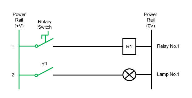
Basic schematic circuit diagram of relay. Electromechanical relays may be connected together to perform logic and control functions acting as logic elements much like digital gates and or etc.
Simple Relay Switch Circuit Diagram
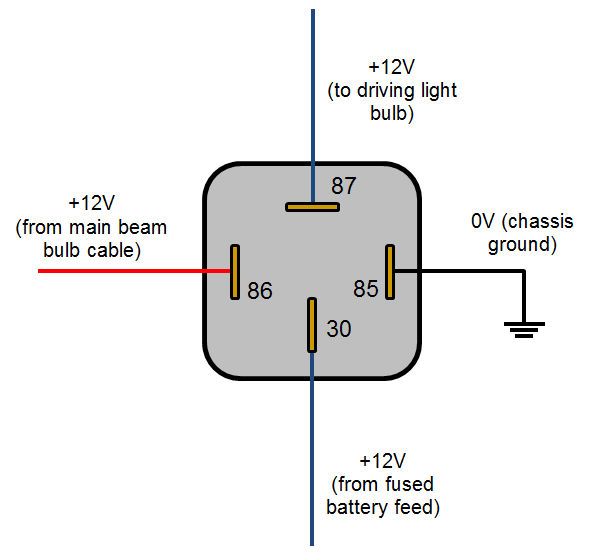
Diagram of a relay. When a relay contact is normally closed nc there is a closed contact when the relay is not energized. The first scheme does not apply the single contact relay energy the upper motor is running the relay is running the lower motor is running. An onoff switch is added for the switching purpose of the relay. To identify the pins of relay you want ohmmeter. Each one of these. Determine the sequence of operations to be performed.
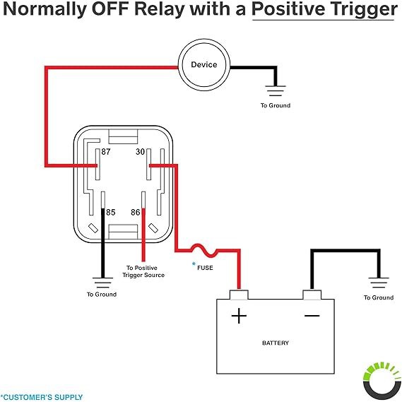
The diode prevents relay from arcing by giving a return path for the energy stored in the magnetic field of coil extending the life of relay. Wiring diagram includes numerous comprehensive illustrations that display the link of assorted items. As shown the power source is given to the electromagnet through a control switch and through contacts to the load. Relays are generally used to switch smaller currents in a control circuit and do not usually control power consuming devices except for small motors and solenoids that draw low. Relay switch circuit diagram working of the basic 5v relay circuit. Relays are generally used to switch smaller currents in a control circuit and do not.
When a relay contact is closed there is a closed contact when the relay is not energized. When a relay contact is open the relay is not energized. Thus the upper contact arm starts to be attracted to the lower fixed arm and thus closes the contacts causing a short circuit for the. In general the following suggestions apply to designing a relay logic diagram. Draw a sketch of the operation process. In either case applying electrical current to the contacts will change their state.
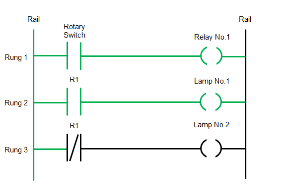
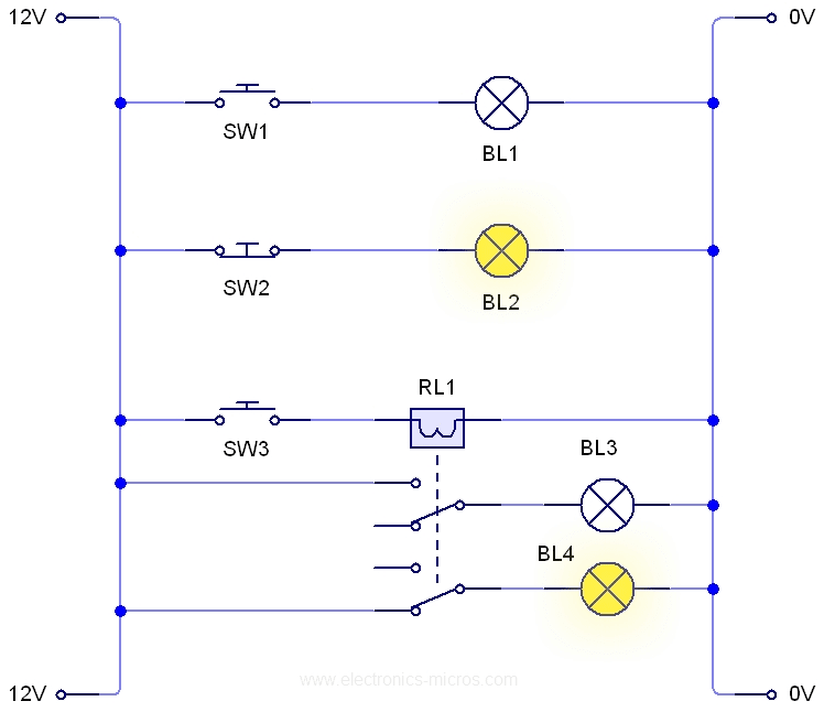
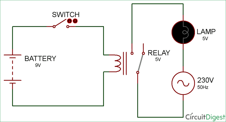
A very common form of schematic diagram showing the interconnection of relays to perform these functions is called a ladder diagram. How can we identify the pins of relays. The transistor allows the hc11 to control the medium sized coil current of relay. The guide incorporates a lot of practical techniques for various situations that you may come across when youre dealing with wiring problems. Various control circuits can be made according to relay power with single and double contact relays. In the above circuit 5v relay is powered by a 9v battery.
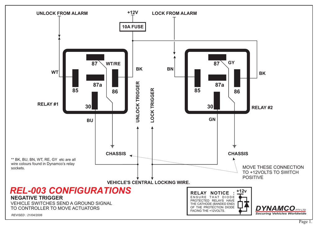
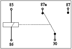
As relay diagrams show when a relay contact is normally open no there is an open contact when the relay is not energized. Ohmmeter is used. 12v relay wiring diagram 5 pin fitfathers 12 v trucks 12 volt relay wiring diagram. Connect the relay with hc11 port pins this is used to control on switches. One with a contact relay and one with a led indicator and the other. The following schematic shows the basic circuit.
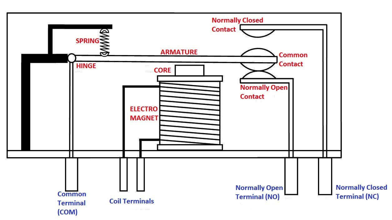
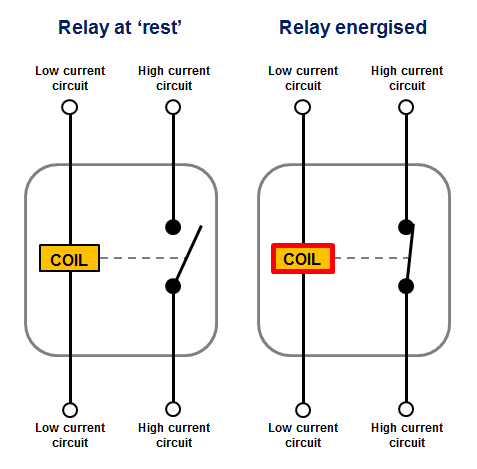
Define the process to be controlled. In either case applying electrical current to the contacts will change their state. Relays switches are used to open and close circuits electromechanically or electronically. At the initial condition when switch is open no current flow through coil hence common port of relay is connected to no normally open pin so the lamp remain off. An iron core is surrounded by a control coil. Here we look at relay switch pin diagram and the different kinds of relay switches.
It consists of directions and diagrams for different varieties of wiring techniques and other products like lights windows and so on. When current starts flowing through the control coil the electromagnet starts energizing and thus intensifies the magnetic field. The diagram shows an inner section diagram of a relay. In the following example diagrams various applications are shown and many applications can be done according to the operating voltage power number of contacts animated gif relay. When the switch is closed current start flowing through the coil and by the concept of electromagnetic induction magnetic field is. Make sure all the components of the system are present in the drawing.
Gallery of Diagram Of A Relay