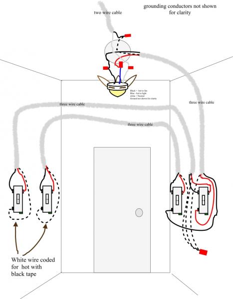
The source is at the switches and the input of each is spliced to the black source wire with a wire nut. Assortment of wiring diagram 3 way switch ceiling fan and light.

Ceiling Fan With Light Wiring Diagram H1 Wiring Diagram
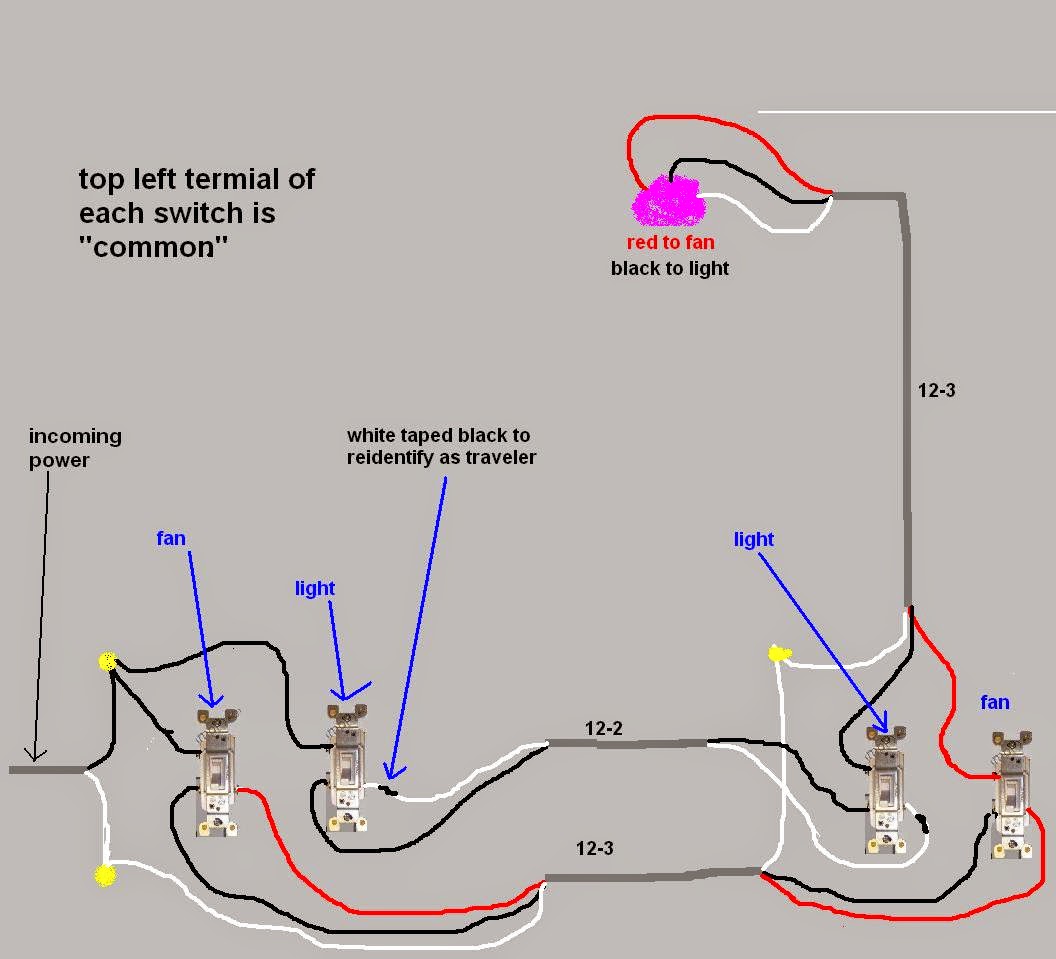
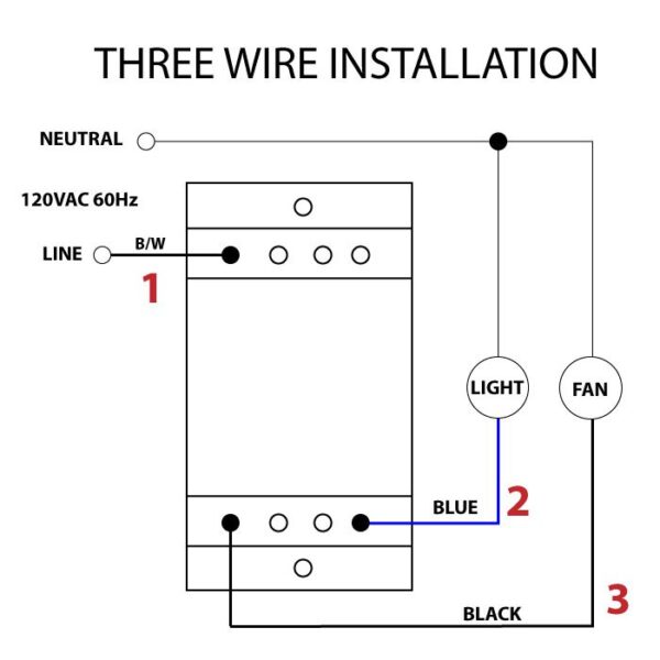
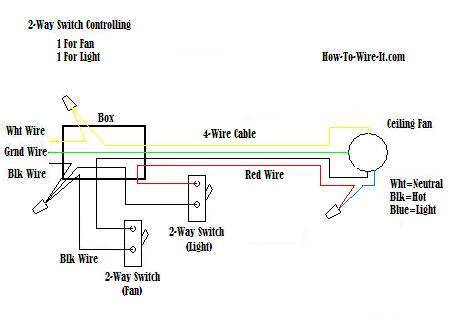
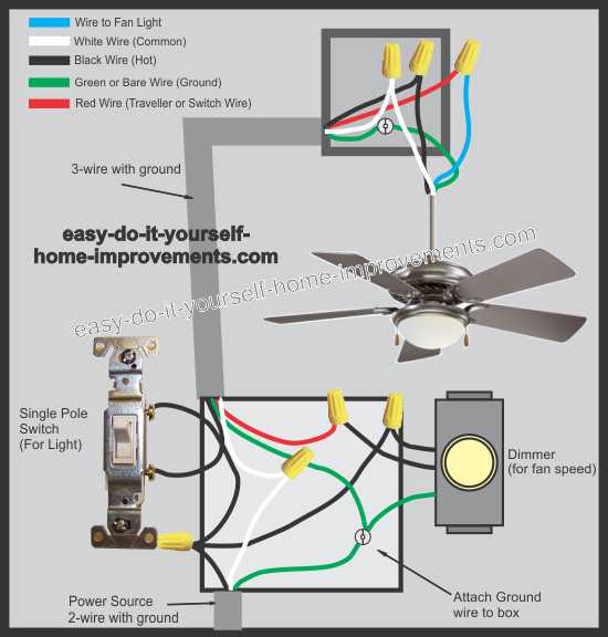
Ceiling fan light switch wiring diagram. The fan control switch is usually combined with a light kit switch with black wire and a 3 way cable red wire. A wiring diagram is a streamlined conventional photographic depiction of an electrical circuit. From the switches 3 wire cable runs to the ceiling outlet box. 1 to l and c1 2 3 slow. The fan control switch usually connects to the black wire and the light kit switch to the red wire of the 3 way cable. Switched lines and neutral connect to a 3 wire cable that travels to the lightfan outlet box in the ceiling.
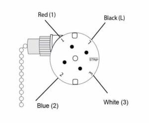
Ceiling fan switch wiring diagram 2 line voltage enters the switch outlet box and the line wire connects to each switch. 1 to l and c1 1 2 med. The light kit will switch to the red wire of the 3 way cable and the fan control switch will connect to the black wire. Speed switch connection table. It shows the elements of the circuit as streamlined forms and also the power and also signal connections in between the devices. Black speed switch three wire capacitor.
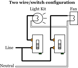
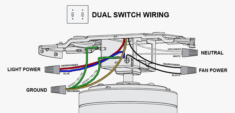
Ceiling fan wiring diagram 2. 1 to l c1 1 and c1 2. Black speed switch with only three terminals connected two wire capacitor. Connects to switched lines and a neutral 3 wire cable that travels through the ceiling lights fan outlet buckles. In this diagram the black wire of the ceiling wire is for the fan and the blue wire is for the light kit. This wiring diagram illustrates the connections for a ceiling fan and light with two switches a speed controller for the fan and a dimmer for the lights.
Ceiling fan wiring diagram 1. In this diagram the black wire for the ceiling fan is for the fan and the blue wire is for the light kit. With the diagrams listed above you can wire a ceiling fan with either a single switch or double switch. Speed switch connection table.
Gallery of Ceiling Fan Light Switch Wiring Diagram