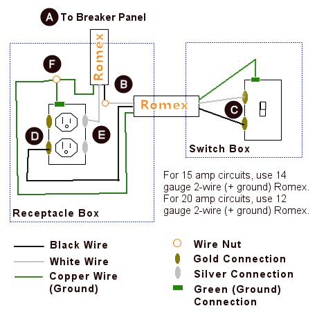
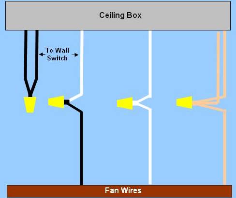
Take a closer look at a ceiling fan wiring diagram. Green the ground.

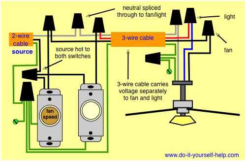
Ceiling Fan Wiring With Remote Control Amp 2 Wall Switches
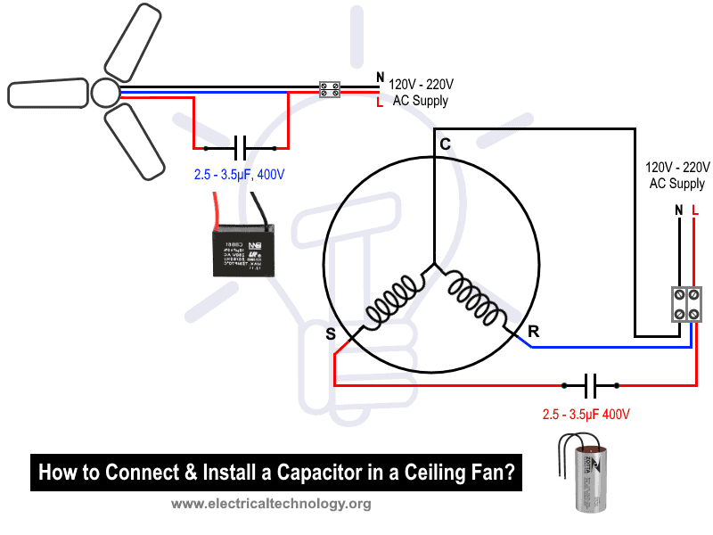
Ceiling fan electrical diagram. Pick the diagram that is most like the scenario you are in and see if you can wire up your fan. The first component is symbol that indicate electric component from the circuit. Need step by step instructions on replacing ceiling fan. The ceiling electrical junction box. There are two things that will be present in any ceiling fan internal wiring diagram. This might seem intimidating but it does not have to be.
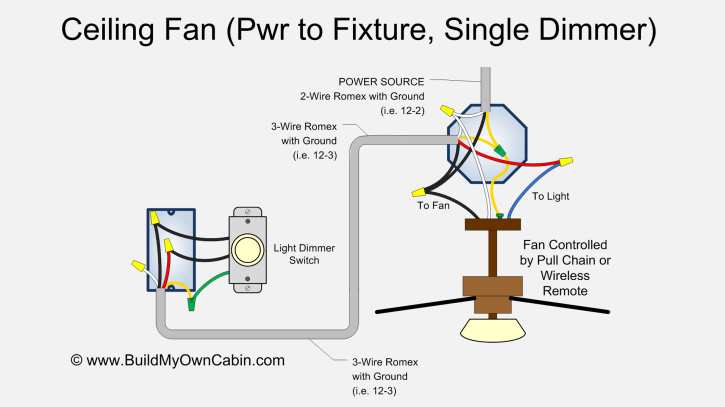
With the below wiring diagrams you can install 90 of ceiling fans no matter the make or model. Installing a ceiling fan. From the switches 3 wire cable runs to the ceiling outlet box. A question we often get asked is where can i find a wiring schematic or wiring diagram for my ceiling fan. Red for the light. Another thing you will find a circuit diagram could be lines.
Wiring diagram 1 power enters at the wall switch box power starting at the switch box this wiring diagram shows the power starting at the switch box where a splice is made with the hot line which passes the power to both switches and up to the ceiling fan and light. Whether it be a hampton bay hunter or another brand of ceiling fan many fans have the same setup in terms of installation. This wiring diagram illustrates the connections for a ceiling fan and light with two switches a speed controller for the fan and a dimmer for the lights. A circuit is generally composed by various components. White the neutral. With these diagrams below it will take the guess work out.
Black for the fan motor. Ceiling fan wiring variations if the ceiling fan does not have a light fixture then the red in the junction box may be capped off. The source is at the switches and the input of each is spliced to the black source wire with a wire nut.
Gallery of Ceiling Fan Electrical Diagram