These tools allow students hobbyists and professional engineers to design and analyze analog and digital systems before ever building a prototype. Component symbols in a circuit diagram are usually placed horizontally or vertically.

Circuit Diagram Wikipedia
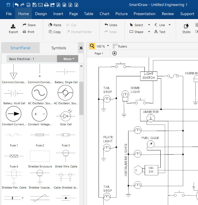
Basic electrical circuit diagram. Piping and instrumentation design. Nagendra krishnapura iit madras electrical circuits are everywhere from tiny ones in integrated circuits in mobile phones and music players to giant ones that carry power to our homes. Basic electrical symbols contain earth electrode cell battery resistor etc. Book now here. Basic electrical home wiring diagrams tutorials ups inverter wiring diagrams connection solar panel wiring installation diagrams batteries wiring connections and diagrams single phase three phase wiring diagrams 1 phase 3 phase wiringthree phase motor power control wiring diagrams. Multimeter includes a galvanometer that is connected in series with a resistance.
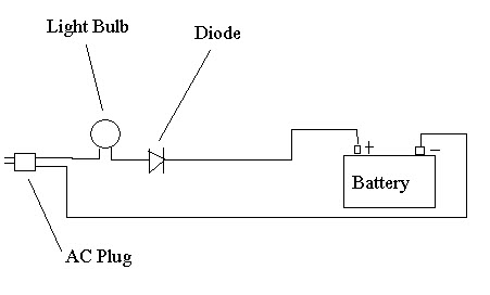
Parts and assembly drawing. In some cases a diagonal line may be used which. Basic home wiring diagrams fully explained home electrical wiring diagrams with pictures including an actual set of house plans that i used to wire a new home. Choose from the list below to navigate to various rooms of this home. The main function of the rectifier is to. Some circuit diagram rules wires or lines in circuit diagrams are usually horizontal or vertical.
Circuitlab provides online in browser tools for schematic capture and circuit simulation. On very rare occasions a component. Multimeter circuit led flasher circuit. The visual and straightforward way to present an electrical circuit should be diagramming it by using basic electrical symbols. Circuit diagrams are drawn. The multimeter is mainly used for the continuity of the windings in a motor.
This course deals with analysis techniques that can be applied to all such circuits. A multimeter is an essential simple and basic electrical circuit that is used to measure voltage resistance and current. Get free android app. Online schematic capture lets hobbyists easily share and discuss their designs while online circuit simulation allows for quick design iteration and accelerated learning about electronics. It is also used to measure dc as well as ac parameters. Whether you are a novice or a professional engineer these basic symbols can help create accurate circuit diagrams in minutes.
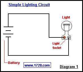
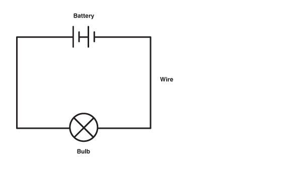
For a lamp we need two wires. 25 off on electrical engineering shirts. The one line diagram is similar to a block diagram except that electrical elements such as switches circuit breakers transformers and capacitors are shown by standardized schematic symbols. A one line diagram or single line diagram is a simplified notation for representing an electrical system. Well first discuss electrical quantities voltage and current relevant to such circuits and learn about basic elementsr l c controlled sources and their properties. The voltage across the circuit can be measured by placing the probes of the multimeter across the circuit.
Plumbing and piping plan. 10 simple electric circuits with diagrams ac circuit for lamp. Well then move. Battery charging is done by means of a rectifier. Kitchen remodels part 1 kitchen remodels part 1 covers planning and design with. One is the neutral wire and the other is the live wire.
Kitchen electrical wiring fully explained photos and wiring diagrams for kitchen electrical wiring with code requirements for most new or remodel projects. Up tp 93 off launching official electrical technology store shop now.
Gallery of Basic Electrical Circuit Diagram