Many thanks for visiting our website to locate brushless dc electric motor diagram. When you need to control a dc motor such as a dc linear actuator you usually need to be able to swap the polarity on the wires going to the motor.
Energy Harvesting Applications Dc Motor Wiring Diagram 4 Wire
4 wire dc motor connection diagram. The construction of the dc motor. It shows the components of the circuit as simplified shapes and the capacity and signal associates amongst the devices. For a visual picture of typical wiring configurations reference the following guide. Hvac condenser fan motor wiring diagram. A wiring diagram is a streamlined conventional pictorial representation of an electrical circuit. Suitable for most motorbikes scooters and quads and even complete classic bike conversions.
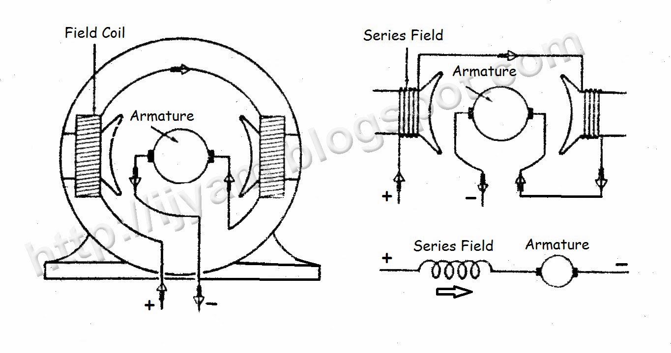
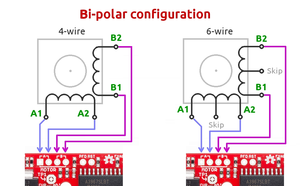
Now for your 4 wire method. It reveals the parts of the circuit as streamlined forms as well as the power and signal links between the gadgets. Mainly there are two types of dc motors. Use figure 2 if your motor has a dual voltage shunt field. Types of dc motor a direct current motor dc is named according to the connection of the field winding with the armature. The dc motor converts the electrical power into mechanical power is known as dc motor.
Finally this guide is intended to be used as a general overview of common condenser unit wiring. 4 wire regulator rectifier is suitable for. Wave regulator rectifier specifications. Motor connections your motor will be internally connected according to one of the diagrams shown below. First one is separately excited dc motor and self excited dc motor. A double pole double throw switch is used for this purpose but you have to wire it up correctly.
Wire a dpdt rocker switch for reversing polarity. Its very helpful to document the location of existing wire connections before removing the condenser fan motor or run capacitor. Motor wiring diagram rpm iii iec integral hp dc motors wiring diagrams besides motor hp frame baldor dc motor wiring diagrams h1 diagramiec quick reference chartb184t baldor 184t frame adjule motor base10 hp single phase baldor electric pressor motor 1725 rpm 215tbaldor reliance dc motors and controlsog 3949 wiring diagrams besides motor hp frame size. Hopefully we provide this is ideal for you. Use a camera to take pictures of the connections and reference the pictures when installing the new condenser fan motor and run capacitor. 12v dc 4 wire regulator rectifier.
If you intend to get another reference about brushless dc electric motor diagram please see more wiring amber you can see it in the gallery below. Dc motor wiring diagram 4 wire wiring diagram is a simplified gratifying pictorial representation of an electrical circuit. These connections are in accordance with nema mg 1 and american standards publication 06. Figure 1 figure 2 single voltage shunt field space heater shunt field arm interpoles series field space heater arm interpoles series field 12. Motor wiring diagram dc. White wire from the condenser fan motor to one side of power on the contactor t1 black wire from the condenser fan motor to other side of power on the contactor t2 brown wire from the condenser fan motor to the capacitor.
Use figure 1 if your motor has a single voltage shunt field. Collection of dc motor wiring diagram 4 wire. The self excited motors are further classified as shunt wound or shunt motor series wound or series motor and compound wound or compound motor.
Gallery of 4 Wire Dc Motor Connection Diagram