A wiring diagram is a streamlined traditional photographic depiction of an electric circuit. All three way switch and 2 way switch wiring diagrams have the same basic components.

Wiring Diagram 3 Way Switch Wiring Diagram Multiple Lights Pdf
3 way switch wiring diagram pdf. The black line wire connects to the common terminal of the first 3 way switch. Step 2 remove the existing faceplates and switches from the gang boxes. Traveler wires are interchangeable. Take a photo of the existing wiring for future reference. Copy and paste it adding a note of your own into your blog a web page forums a blog comment your facebook account or anywhere that someone would find this page valuable. If you have any problems with these switches it may be best to call an electrician.
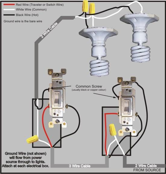
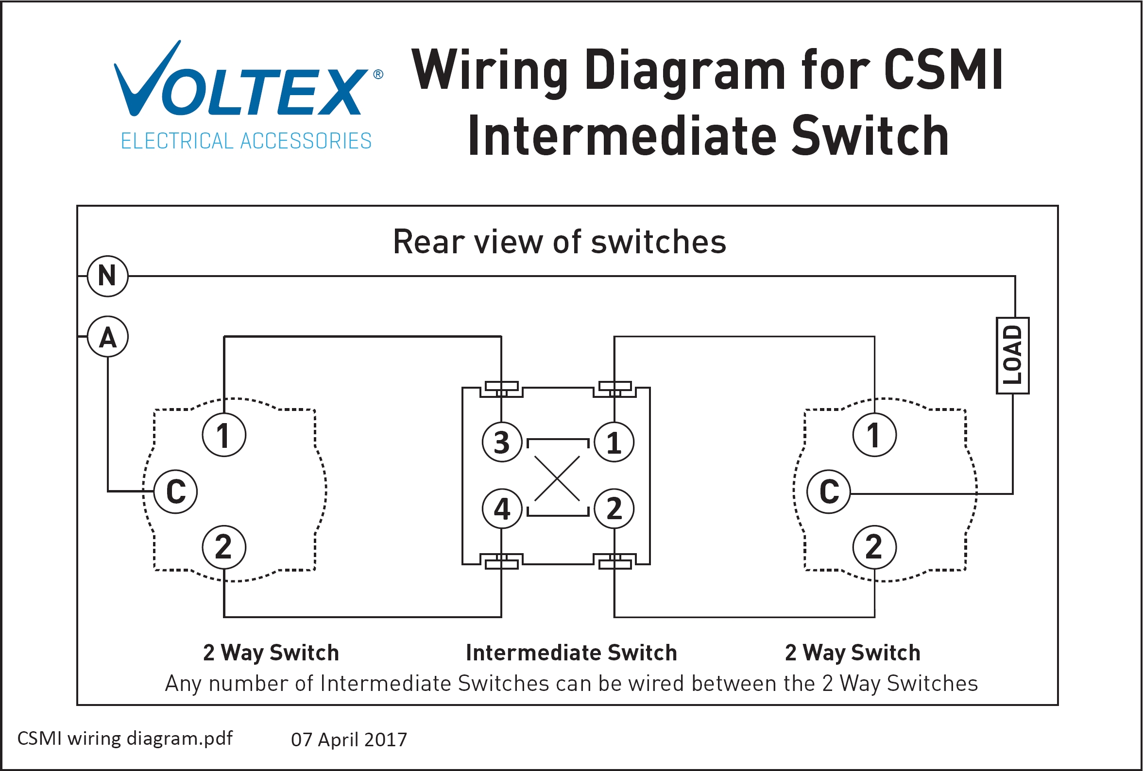
How 4 way switch function. Installation 3 way step 1 turn off the power at the circuit breaker. Three wire cable runs between the switches and 2 wire cable runs to the light. Using the electrical wiring diagram body electrical diagnosis course l652 3 one of the keys to a quick and successful electrical diagnosis is correctly using the lexus electrical wiring diagram or ewd. Step 3 confirm that each gang box contains a neutral wire typically white. 4 way switch wiring need two 3 way switches one at each end and then as many 4 way switches as you want in between.
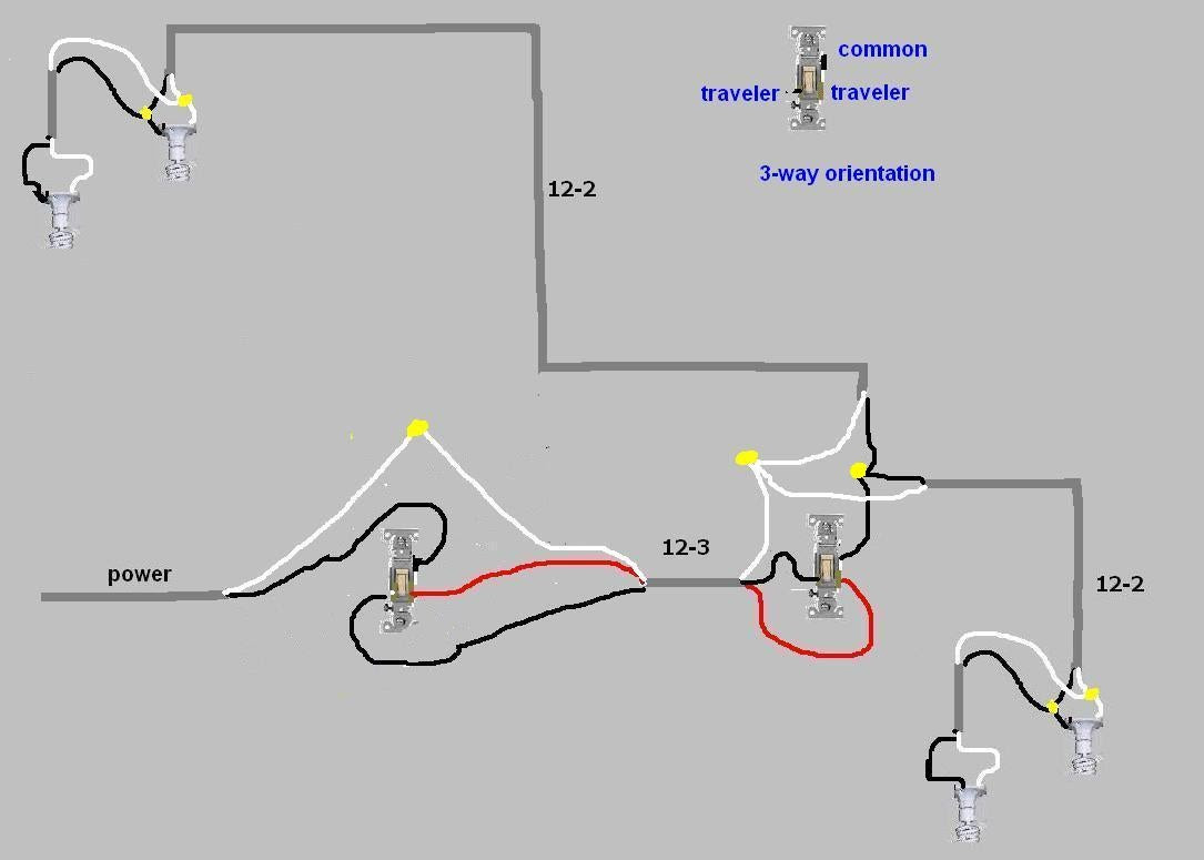
Wires consisting of a line a load a neutral a pair of travelers and two 3 way switches. A 3 wire nm connects the traveler terminals of the first and second 3 way switch together. Typical 3 way switch wiring nm cable. Assortment of 3 way switch wiring diagram pdf. One 4 way switch. Components of 3 way switch wiring.
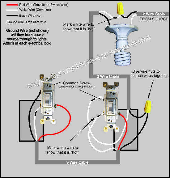
In the 1st diagram below a 2 wire nm cable supplies power from the panel to the first switch box. Unfortunately not all 3 way switches are wired the conventional way. Variety of 3 way switch wiring diagram pdf. Wiring diagram 3 way switch with light at the end in this diagram the electrical source is at the first switch and the light is located at the end of the circuit. Everything from connector. Click on the html link code below.
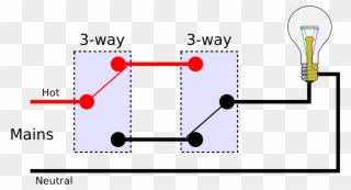
The black and red wires between sw1 and sw2 are connected to the traveler terminals. See alternate 3 way switch wiring configuration for another way 3 way switches may be wired. It shows the parts of the circuit as simplified forms and also the power and signal links in between the tools. If you are trying to troubleshoot a 3 way switch operation then you will need to identify the function of each wire. It shows the components of the circuit as simplified forms and the power and also signal links in between the gadgets. The diagrams below show the conventional wiring for 3 way switches.
2 wire cable runs from the light to the first switch and then 3 wire is run between all the switches. The ewd is not just a book of wiring diagrams but an information resource for anything electrical on the vehicle. A wiring diagram is a simplified standard pictorial representation of an electrical circuit. If there are no neutral wires present you may need to run additional.
Gallery of 3 Way Switch Wiring Diagram Pdf