Take a closer look at a 3 way switch wiring diagram. For example a long hallway or stairway might use a pair of three way.

Rd 9949 Double Rocker Switch Wiring Diagram Internal
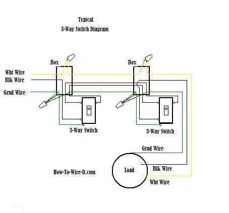
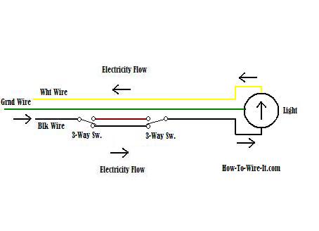
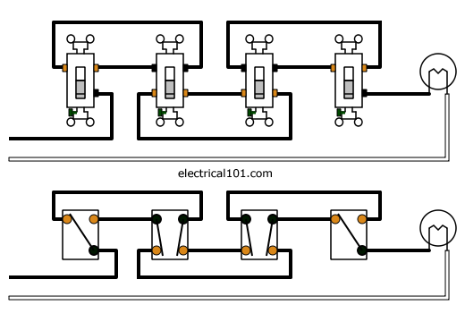
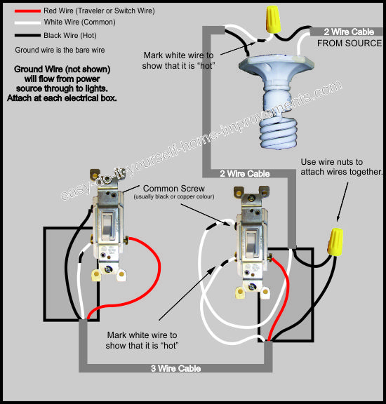
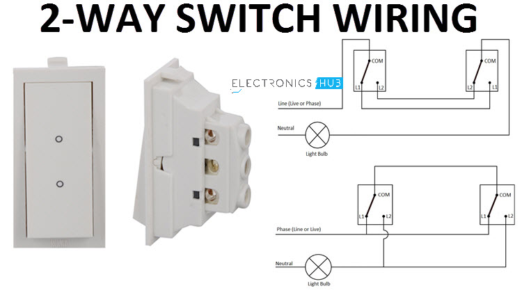
3 way switch internal diagram. Pick the diagram that is most like the scenario you are in and see if you can wire your switch. The ground wire is pigtailed with a wire connector at the switch boxes and the ceiling box. The diagrams below show the conventional wiring for 3 way switches. If you have any problems with these switches it may be best to call an electrician. 3 way switch wiring diagram. Wiring diagram 3 way switch with light at the end in this diagram the electrical source is at the first switch and the light is located at the end of the circuit.
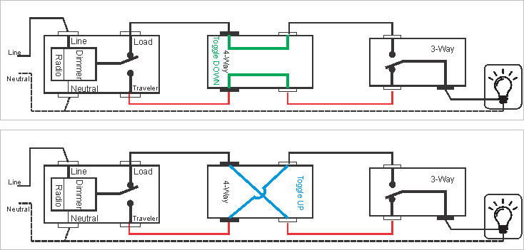
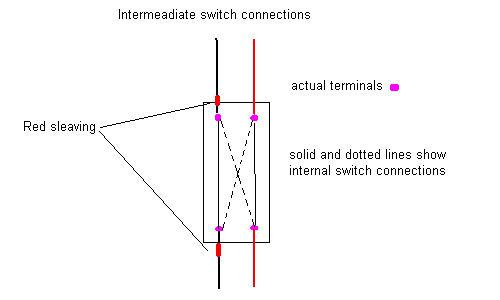
The white wire becomes the energized switch leg as indicated by using black or red electrical tape. The black and red wires between sw1 and sw2 are connected to the traveler terminals. 4 way switch schematics can also be used for intermediate switches. A 3 way switch wiring diagram is a simple drawing showing how to connect the wires to each of the four screws on the 3 way switch. 3 way switch diagram 2 above shows the electricity source starting at the fixture. Most common is the single pole switch the type used to control a light fixture from a single locationthe next most common is the three way switch which is commonly used to control a light fixture from two different locations.
The diagram below is based on the video you watched above. Fixture between two three way switches. This 4 way switch diagram 1 shows the power source starting at the left 3 way switch. What is the black screw for on a 3 way switch diagram. Four way switch wiring diagrams. This wire diagram shows the wiring for source power into the first three way switch then 3 wire cable to the next 3 way light switch and then on to the light or light fixtures.
The 4 ways are in between. The white wire of the cable going to the switch is attached to the black line in the fixture box using a wire nut. A typical four way switch wiring diagram. The basic 3 way switch wiring diagram this is the most common and the easiest wiring diagram to follow of any of the wiring diagrams for a 3 way switch circuit. Unfortunately not all 3 way switches are wired the conventional way. This might seem intimidating but it does not have to be.
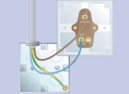
The white wire of the cable going to the switch is attached to the black line in the fixture box using a wirenut. The load wire is in one 3 way switch box and the line from the power source is in the other 3 way switch box. Wall switches used to control ceiling light fixtures or other fixtures come in three types. Power through switch light is controlled by two three way switches with the light between the switches and the power first going through a switch then to the light and onto the second three way switch. What is a 3 way switch wiring diagram. With these diagrams below it will take the guess work out of wiring.
Three wire cable runs between the switches and 2 wire cable runs to the light. This 4 way switch diagram 2 shows the power source starting at the fixture. See alternate 3 way switch wiring configuration for another way 3 way switches may be wired.
Gallery of 3 Way Switch Internal Diagram