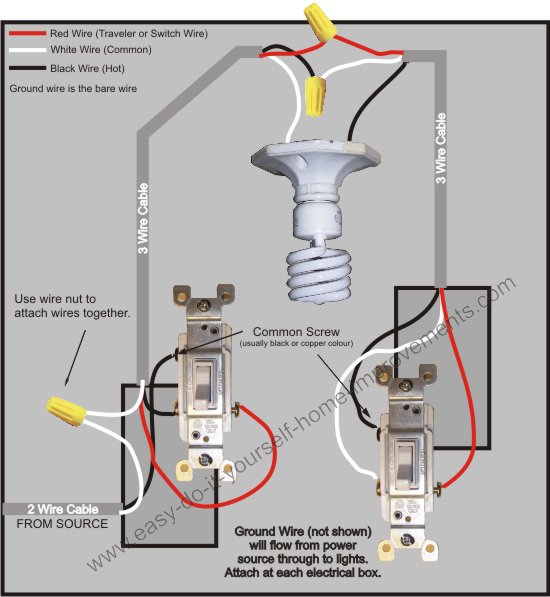
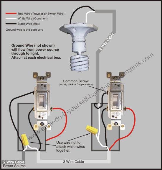
This 3 way light switch wiring diagram shows how to do the light switch wiring and the light when the power is coming to the light fixture. What is the black screw for on a 3 way switch diagram.

California 3 Way Switching Doityourself Com Community Forums
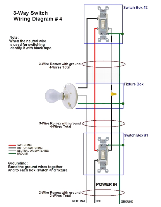
3 way switch diagram. The black screw on a 3 way switch diagram is for the continuous hot wire that comes from the circuit panel or for the feed wire that runs up to the light fixture. This might seem intimidating but it does not have to be. 3 way switch wiring diagram. 3 way switches have three terminals one common usually black color and one pair of travelers usually brass color. The white wire becomes the energized switch leg as indicated by using black or red electrical tape. 3 way switch wiring diagrams wiring diagram 3 way switch with light at the end.
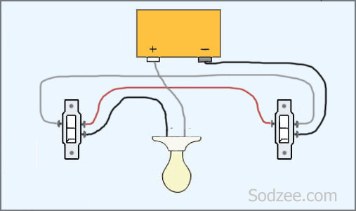
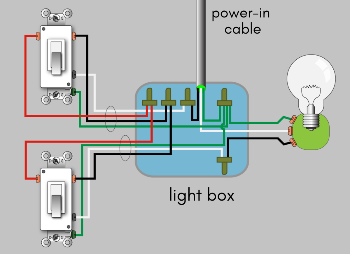
If you are trying to troubleshoot a 3 way switch operation then you will need to identify the function of each wire. The ground wire is pigtailed with a wire connector at the switch boxes and the ceiling box. Power through switch light is controlled by two three way switches with the light between the switches and the power first going through a switch then to the light and onto the second three way switch. Wires consisting of a line a load a neutral a pair of travelers and two 3 way switches. All of the switches shown below are 3 way. The source in this circuit is at the first switch and the light fixture is.
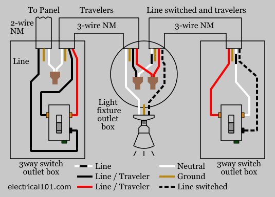
The black hot wire connects to the far right switchs common terminal. With these diagrams below it will take the guess work out of wiring. Pick the diagram that is most like the scenario you are in and see if you can wire your switch. A 3 wire nm connects the traveler terminals of the first and second 3 way switch together. The basic 3 way switch wiring diagram this is the most common and the easiest wiring diagram to follow of any of the wiring diagrams for a 3 way switch circuit. 3 way switch diagram 2 above shows the electricity source starting at the fixture.
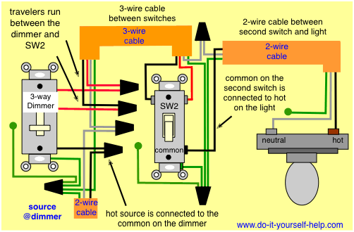
All three way switch and 2 way switch wiring diagrams have the same basic components. Take a closer look at a 3 way switch wiring diagram. A 3 way switch wiring diagram is a simple drawing showing how to connect the wires to each of the four screws on the 3 way switch. In the 1st diagram below a 2 wire nm cable supplies power from the panel to the first switch box. Three way switch wiring with light middle. Typical 3 way switch wiring nm cable.
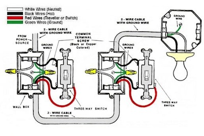
This wire diagram shows the wiring for source power into the first three way switch then 3 wire cable to the next 3 way light switch and then on to the light or light fixtures. The diagram below is based on the video you watched above. With conventional wiring the common wire from one switch connects to line the common wire from the other switch connects to the load lights. Electricians call the continuous hot wire the line wire. In this diagram power enters the fixture box. Traveler wires are interchangeable on each switch.
3 way switch wiring with. Red and blue wires link traveler terminals of both switches. The white wire of the cable going to the switch is attached to the black line in the fixture box using a wire nut. In this diagram the electrical source is at the first switch and the. Fixture between two three way switches. The black line wire connects to the common terminal of the first 3 way switch.
Gallery of 3 Way Switch Diagram