4 wire reversible psc motor. To use three phase electricity a motor needs windings spaced 120 degrees apart.

3 Phase Motor Wiring Diagram Star Delta H1 Wiring Diagram
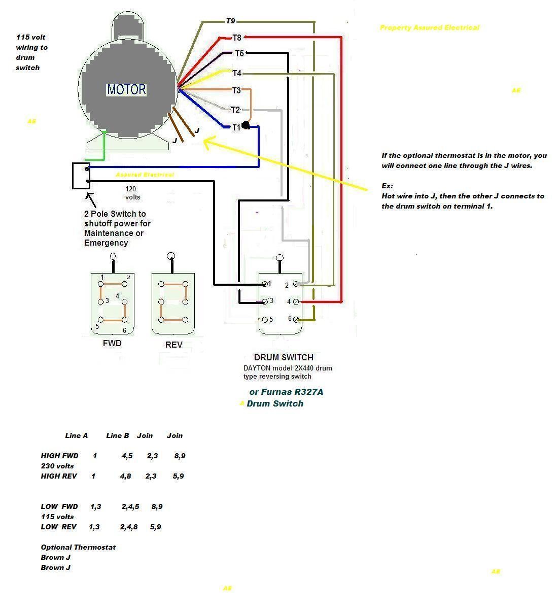
3 phase motor wiring diagram. Three phase power from the utilities is connected to the main breaker through three phase energy meter. 3 wire 3 phase motor. 4 wire reversible psc motor with a triple pole double throw switch. Three phase electric motors use three different electric legs with a 13 cycle lag between them. Motor starters have a set of contactors. In the united states for low voltage motors below 600v you can expect either 230v or 460v.
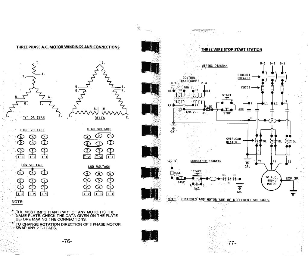
The figure below shows schematic diagram for industrial three phase wiring. Three phase motors are more efficient than single phase motors and are commonly found in applications requiring more than 75 horsepower. How to wire a baldor 3 phase motor. Ac80 ac90 ac100 single phase motors. Ac65 ac80 ac90 ac100 three phase motors. A three phase motors large size and high starting torque usually limit its use to industrial settings.
The motors starter wires directly to the motors wire terminals. A three phase motor must be wired based on the diagram on the faceplate. When the motors switch is turned on voltage flows through the contactors coil creating a magnetic field. The voltage cycle of each line lags its predecessor by 120 degrees l2 reaches its peak voltage after l1 and l3 reaches its peak voltage after l2. I am trying to wire up a two speed 6 wire 3 phase motor to run at its highest speed. Wiring diagram 6 lead 3 phase 480 volt motor wiring library 3 phase motor wiring diagram 6 wire wiring diagram contains the two examples 3 phase motor wiring diagram 12 leads.
Capacitor motor single phase wiring diagrams always use wiring diagram supplied on motor nameplate. The first step is to figure out the voltage of your phases. I believe i need to wire u1 v1 w1 to power and leave u2 v2 w2 disconnected. Star delta y δ 3 phase motor starting method by automatic star delta starter with timer. Assortment of 3 phase motor starter wiring diagram pdf. The motor will supply the same amount of power but with a different load.
June 15 2020 wiring diagram by anna r. Now for the purposes. 3 phase motor wiring diagram 6 wire. The power in the main breaker is then given to various busbars. As 183 wiring diagram with switch. Higginbotham phase 220 vac motor wiring diagrams wiring diagram 3 phase motor wiring diagram 12 leads wiring diagram contains numerous comprehensive illustrations that present the relationship of varied things.
A wiring diagram is a streamlined conventional photographic representation of an electrical circuit. Below is the motor data plate and whats left of the wiring diagram. That being said there is a wide range of different motors and what you have on hand can be completely different. A three wire three phase circuit is usually more. How to wire a 3 phase motor and vfd duration. 3 phase motor starter wiring diagram pdf.
Although the national electric code does not specify specific conductor colors for three phase current it is common to use black red and blue wires to identify lines l1 l2 and l3 respectively. It shows the parts of the circuit as simplified shapes and also the power and also signal links in between the tools. Three phase motor power control wiring diagrams three phase motor connection schematic power and control wiring installation diagrams. Ac80 ac90 ac100 single phase motors.
Gallery of 3 Phase Motor Wiring Diagram