How to wire a contactor and overload. Higginbotham phase 220 vac motor wiring diagrams wiring diagram 3 phase motor wiring diagram 12 leads wiring diagram contains numerous comprehensive illustrations that present the relationship of varied things.

Aim Manual Page 35 Three Phase Motors Motor Application
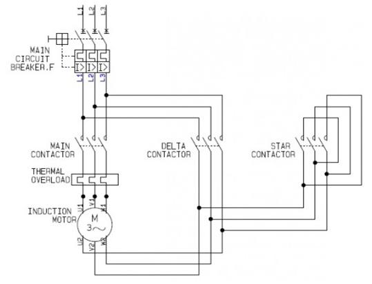
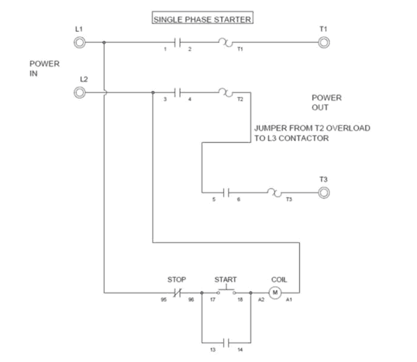
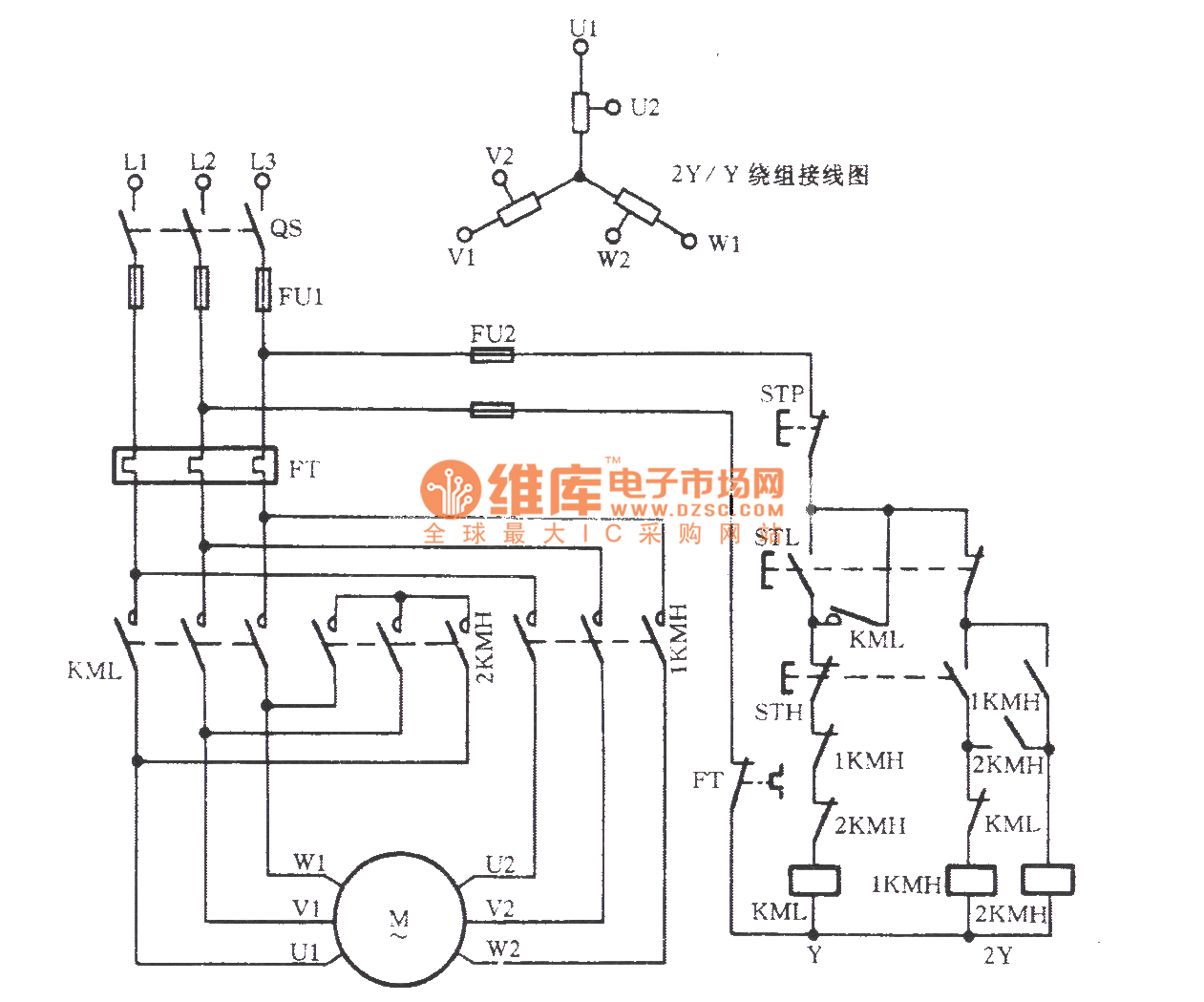
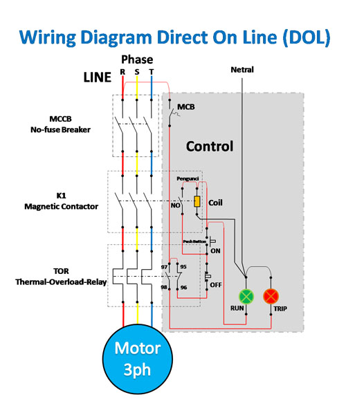
3 phase motor connection diagram. If not the arrangement wont work as it should be. Three phase motor connection stardelta without timer power control diagrams. This is a start stop push button control schematic which includes contactor m overload. Star delta y δ 3 phase motor starting method by automatic star delta starter with timer. But before we will disuse. A three pole breaker with an appropriate current rating is used for connecting a three phase motor.
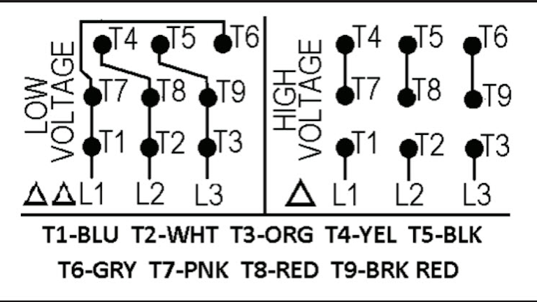
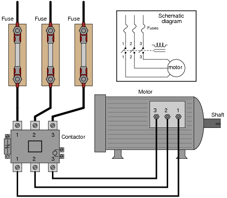
Three phase motor connection schematic power and control wiring installation diagrams. The first step is to figure out the voltage of your phases. Each component ought to be placed and linked to different parts in particular manner. A three phase motor must be wired based on the diagram on the faceplate. Proper care should be taken while connecting three phase wires to the motor because the direction of rotation can be reversed simply by reversing any of the two wires of three phase system. Contactor design and rating contactor nameplate.
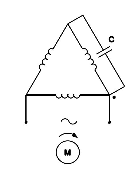
Assortment of 3 phase motor starter wiring diagram pdf. Although the national electric code does not specify specific conductor colors for three phase current it is common to use black red and blue wires to identify lines l1 l2 and l3 respectively. June 15 2020 wiring diagram by anna r. That being said there is a wide range of different motors and what you have on hand can be completely different. Motor starter schematic and wiring diagram. Single phase motor wiring diagram with capacitor baldor single phase motor wiring diagram with capacitor single phase fan motor wiring diagram with capacitor single phase motor connection diagram with capacitor every electrical arrangement is made up of various unique pieces.
In the united states for low voltage motors below 600v you can expect either 230v or 460v. A wiring diagram is a streamlined conventional photographic representation of an electrical circuit. Wiring diagram 6 lead 3 phase 480 volt motor wiring library 3 phase motor wiring diagram 6 wire wiring diagram contains the two examples 3 phase motor wiring diagram 12 leads. It shows the parts of the circuit as simplified shapes and also the power and also signal links in between the tools. 3 phase motor starter wiring diagram pdf. Ac blower motor wiring diagram furthermore 3 phase star delta motor connection diagram besides dc electrical motor wiring diagram further 813 tube lifier schematic furthermore three phase induction motor rotor and stator.
Wiring diagram book a1 15 b1 b2 16 18 b3 a2 b1 b3 15 supply voltage 16 18 l m h 2 levels b2 l1 f u 1 460 v f u 2. The voltage cycle of each line lags its predecessor by 120 degrees l2 reaches its peak voltage after l1 and l3 reaches its peak voltage after l2. Three phase motors are more efficient than single phase motors and are commonly found in applications requiring more than 75 horsepower. The wiring diagram for connecting thee phase motor to the supply along with control wiring is shown in figure below.
Gallery of 3 Phase Motor Connection Diagram