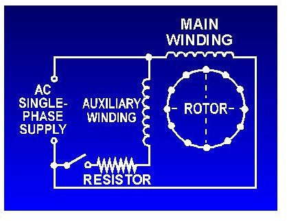
It is evident from the phasor diagram that the current through the starter winding is leads the voltage v by a small angle and the current through the main winding im lags the applied voltage. Honestly we also have been remarked that century ac motor.

Wiring Diagrams Royal Range Of California
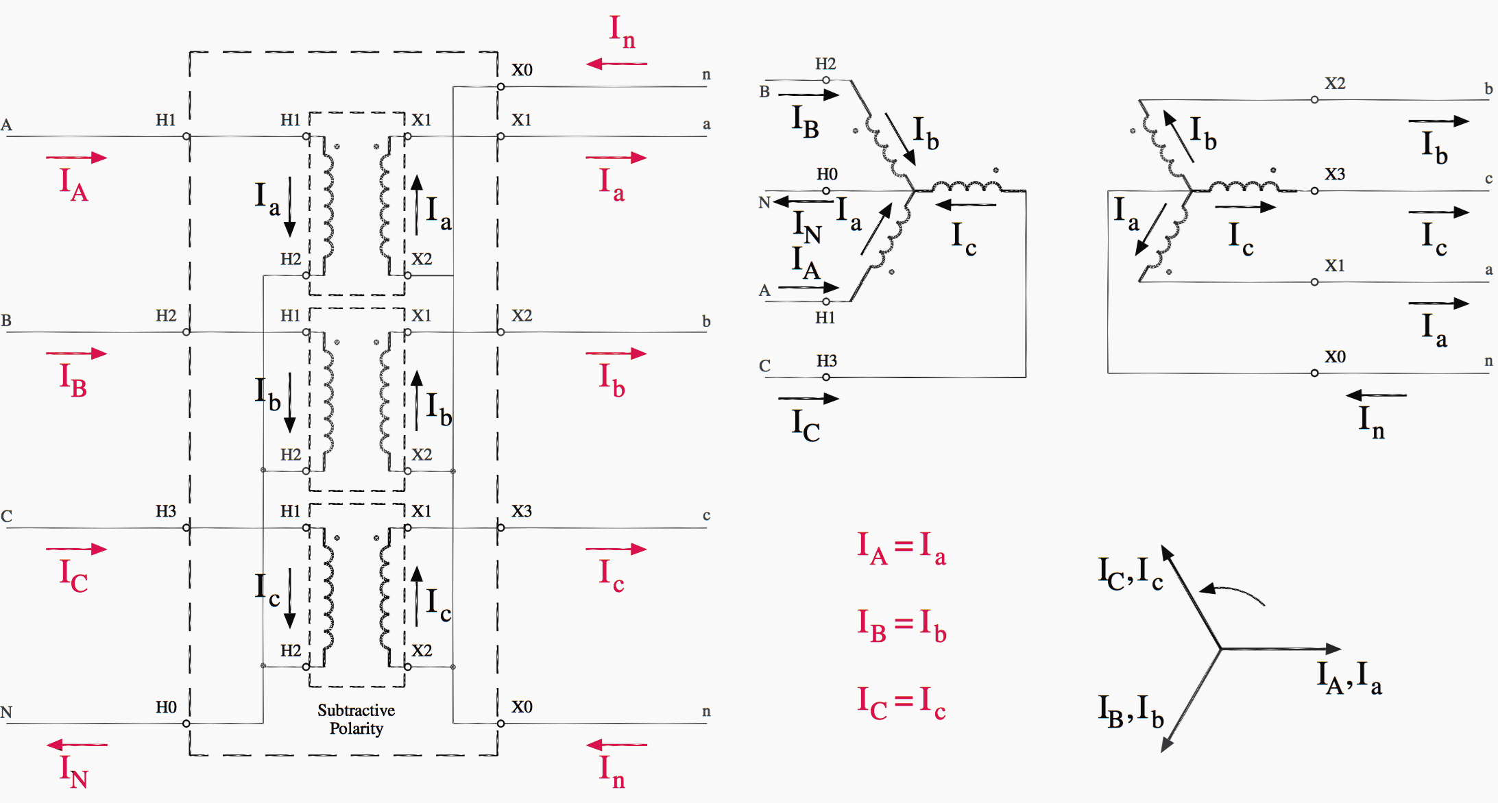
3 phase 240v motor wiring diagram. Both 9 wire and 12 wire motors can be connected for high or low voltage operation. February 11 2020 april. In the us 240v power is provided to homes and small buildings as a 120240v 1p3w power circuit. Connect the two wires in the wiring box together as specified by the wiring diagram for a 240 volt connection. Some 3 phase motors have 2 wire and 3 wire connection diagrams ether on the maker plate or under the connection box plate. A 9 wire motor can only be connected in a wye configuration whereas a 12 wire motor can be connected in either a wye or delta configuration.
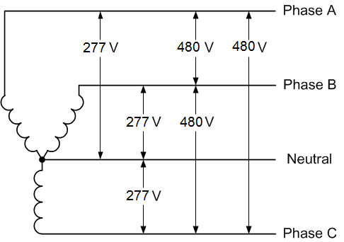
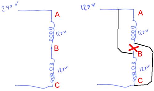
Open the connection box and see if it has 3 6 9 or 12 wires. 120 240v single phase 3 wire 1p3w 120240v 1 phase 3 wire. It shows the components of the circuit as simplified shapes and the facility and signal associates in the middle of the devices. Assortment of 240v motor wiring diagram single phase. 240v motor wiring diagram single phase single switch wiring diagram 110 single circuit diagrams wire center u2022 rh casiaroc co. In the us 120 240v 1 phase 3 wire is the standard for homes and 240v 3 phase open delta is the standard for small buildings with large loads.
Magnetek compressor motor wiring diagram magnetek century ac motor throughout century ac motor wiring diagram image size 817 x 522 px. 6 and up wires is reversible and may be able to convert from a 3 phase line to a 2 phase line depending on where you live. It is important to point out from the phasor diagram that the phase difference between im and is is almost 80 degrees as against 30 degrees in a split phase induction motor. It is to be. Century ac motor wiring diagram 115 230 volts century 34 hp motor inside century ac motor wiring diagram image size 760 x 578 px. October 5 2018 april 12 2020 wiring diagram by anna r.
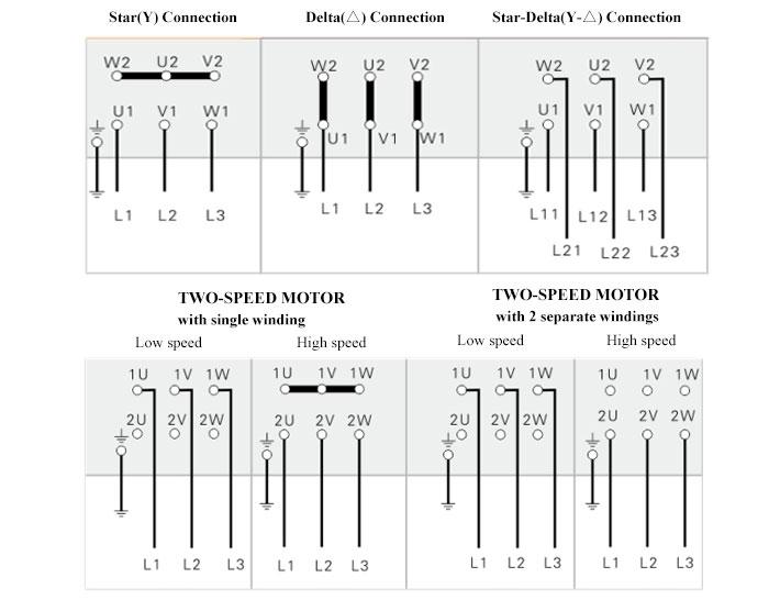
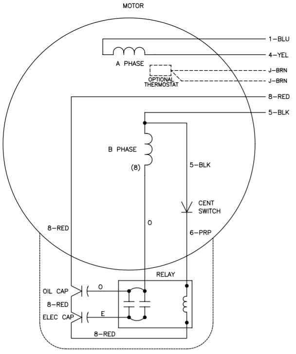
Click on the image to enlarge and then save it. 3 phase motor wiring diagram 9 leads. 3 phase motor wiring will definitely help you in increasing the efficiency of your work. Three phase wiring diagrams split phase motor dual voltage reversible rotation capacitor motor single phase wiring diagrams always use wiring diagram supplied on motor nameplate w2 cj2 ui vi wi w2 cj2 ui vi wi a cow voltage y high voltage z t4 til t12 10 til t4 t5 ali l2 t12 ti blu t2 wht t3org t4 yel t5 blk t6 gry t7 pnk direct on line dol motor starter direct on line dol motor starter 3 wiring of dol devices for 230v single phase with 230v coil wiring of additional start stop. In parts of the world 240v single phase 2 wire is the standard for homes. Actual power company voltage varies 220v 230v 240v by region but to simplify were going to focus on 240v.
Help wire a century electric ac motor doityourself community for century ac motor wiring diagram image size 473 x 383 px. Wiring diagram pics detail. Higginbotham diagram 9 leads wiring diagram for 3 phase motor leads 3 phase motor wiring diagram 9 lead 3 phase 240480v wiring diagram smart intelligent 3 phase motor schematic wiring diagram 3 phase motor wiring diagram. Thus a capacitor start induction run motor produces a better rotating magnetic field than the split phase motors. 240 volt 3 phase motor wiring diagram wiring diagram is a simplified enjoyable pictorial representation of an electrical circuit. Step 5 connect the two hot wires coming from the switch to the remaining two motor wires with wire nuts.
L1 to t1 l2 to t2 l3 to t3 t4 to t7 t5 to t8 and t6 to t9. 3 wires is fixed forward. Repeat the process for the second incoming wire and motor wire. Strip the ends of the wires if necessary and twist a wire nut onto the pair of wires. Single voltage motor wiring step 1 read the motor. Strip the ends of the wires and connect one incoming wire to one motor wire.
The other 9 wires would be connected as in a 9 wire motor note in a 9 wire motor the equivalent of t10 t11 and t12 are internally connected together. 3 phase motor wiring.
Gallery of 3 Phase 240v Motor Wiring Diagram