24 volt battery diagram wiring diagram and schematics how to configure a battery bank 12 volt battery wiring layout 4 battery 24 volt wiring diagram pdf imageresizertool 4 battery 24 volt wiring diagram pdf to her with wiring diagram ford 3000 sel tractor also more build solar voltage regulator along with disconnect. Mks2pidc mks2pi dc b.
24 Volt Relay Wiring Diagram 120 H1 Wiring Diagram
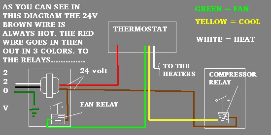
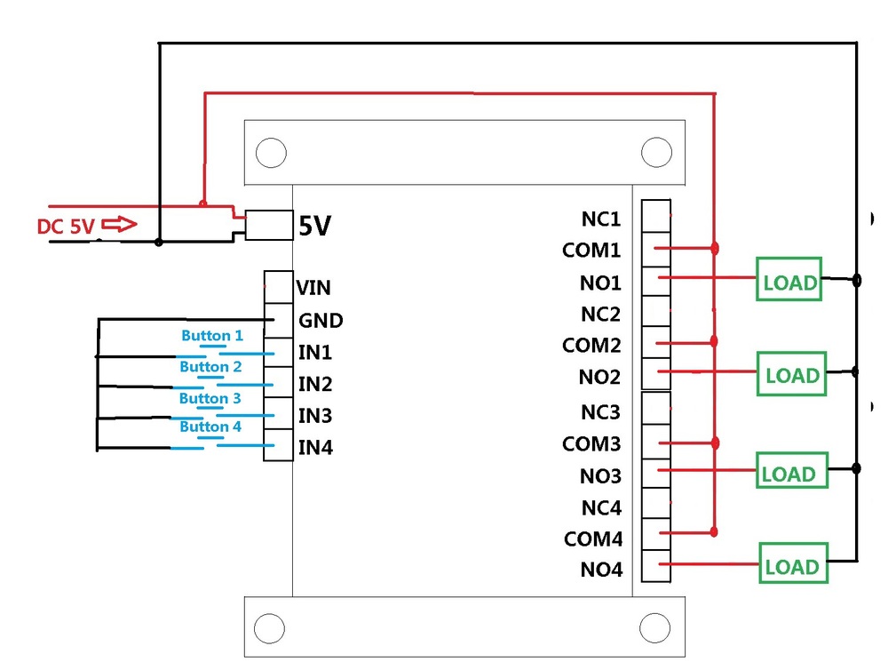
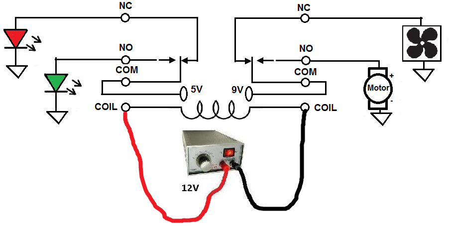
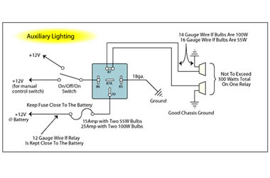
24 volt relay wiring diagram. Pcm energizes two relays. The square relay pinout shows how the relay socket is configured for wiring. As you can see there is absolutely no difference between the square type and the round type other than the ratings on the relay. For the next step you have to include the relay arm and then the relay will normally close. The wiring diagram on the opposite hand is particularly beneficial to an outside electrician. The fans are controlled by the pcm engine computer.
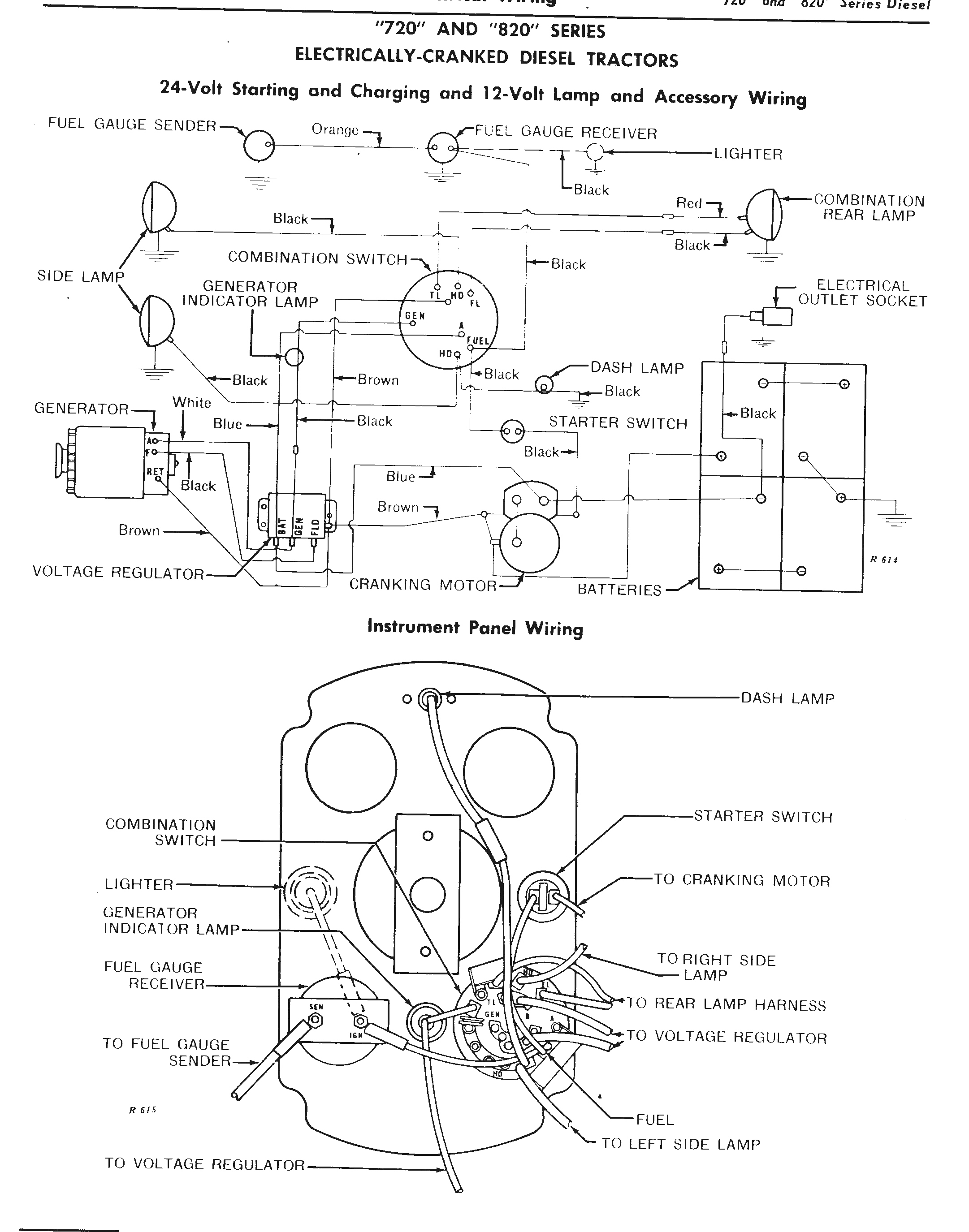
You will be able to know precisely if the projects needs to be finished which makes it much easier for you to effectively handle your time. This pinout image is only a 2 pole diagram for room on the page purposes but you can get the picture here with this one since a 3 pole will just have 1 more set of contacts. If the wiring of your direct current relay the procedure you would undertake would include a 24 volt direct current negative which is the signal ground and a 24 volt direct current negative. Assortment of 12 volt relay wiring diagram. John deere 24 volt electrical systems on electric start 70 and diesels. John deere starter relay wiring diagrams.
12 24 24 yes. Sometimes wiring diagram may also refer to the architectural wiring program. Videos on youtube. The tm i have covers only pre side console the parts counter at your jd dealer should be able to print that diagram from their parts. Wiring diagram 710529a replaces 7105290 1208 7105292 24 volt field connection comp status led status led description green power module has power red trip thermostat demand signal y1 is present but the compressor is not running yellow alert flash code 1 long run time compressor is running extremely long run cycle yellow alert flash code 2 system pressure trip discharge or suction pressure out of limits or compressor overloaded yellow alert flash code 3 short cycling. The simplest approach to read a home wiring diagram is to begin at the source or the major power supply.
John deere 12 volt wiring diagram including john deere 24 volt system together with john deere starter relay including wiring diagram john. 24 volt relay schematic symbol. Wiring diagram sheets detail. Watch a few videos on youtube on basic automotive electrical testing how to read an use a wiring diagram. If you pull the relay out. 3 pos switch wiring diagram tractor parts repair and images john deere wiring schematic wordpress.
Otherwise they work exactly the same. Built in ω. 24 3pdt 3 pole no. In a 24 volt dc direct current relay the twenty four volt direct current is classed as the input and the relay is the output. Multiple 12v relay wiring diagram wiring diagram 12 volt relay wiring diagram. In addition wiring diagram provides you with time body by which the tasks are to be completed.
Then you have connect the photo sensor negative black to the photo sensor. 24 volt battery wiring diagram. 12 volt relay wiring diagram bosch relay wiring diagram 5 pole fresh 5 pin relay wiring diagram inspirational pin relay wiring. Buy a volt meter. How to operate relay omron mk2p 220vac. 1 pcs relay omron mks2pi 24vdc socket 2 pcs accu 12 volt serie up 24v dc sesuaikan tdr berikut gambar rangkaian utama dan wiring diagramnya.
Wiring diagram also offers useful recommendations for projects that might require some. Click on the image to enlarge and then save it. Octal base general purpose relays. Check for b voltage at the relays at pins 30 85. Long life minimum electrical operations. 12 volt spotlight wiring diagram manual e books 12 volt relay wiring diagram.
12 volt relay wiring. Find yourself a wiring diagram.
Gallery of 24 Volt Relay Wiring Diagram