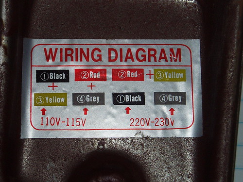
I have an older 1950s 1960s capacitor start two voltage single phase motor that i can not figure out the correct wiring. Collection of electric motor wiring diagram 110 to 220.

Yg 8428 Switch Along With 230 Volt Single Phase Motor Wiring
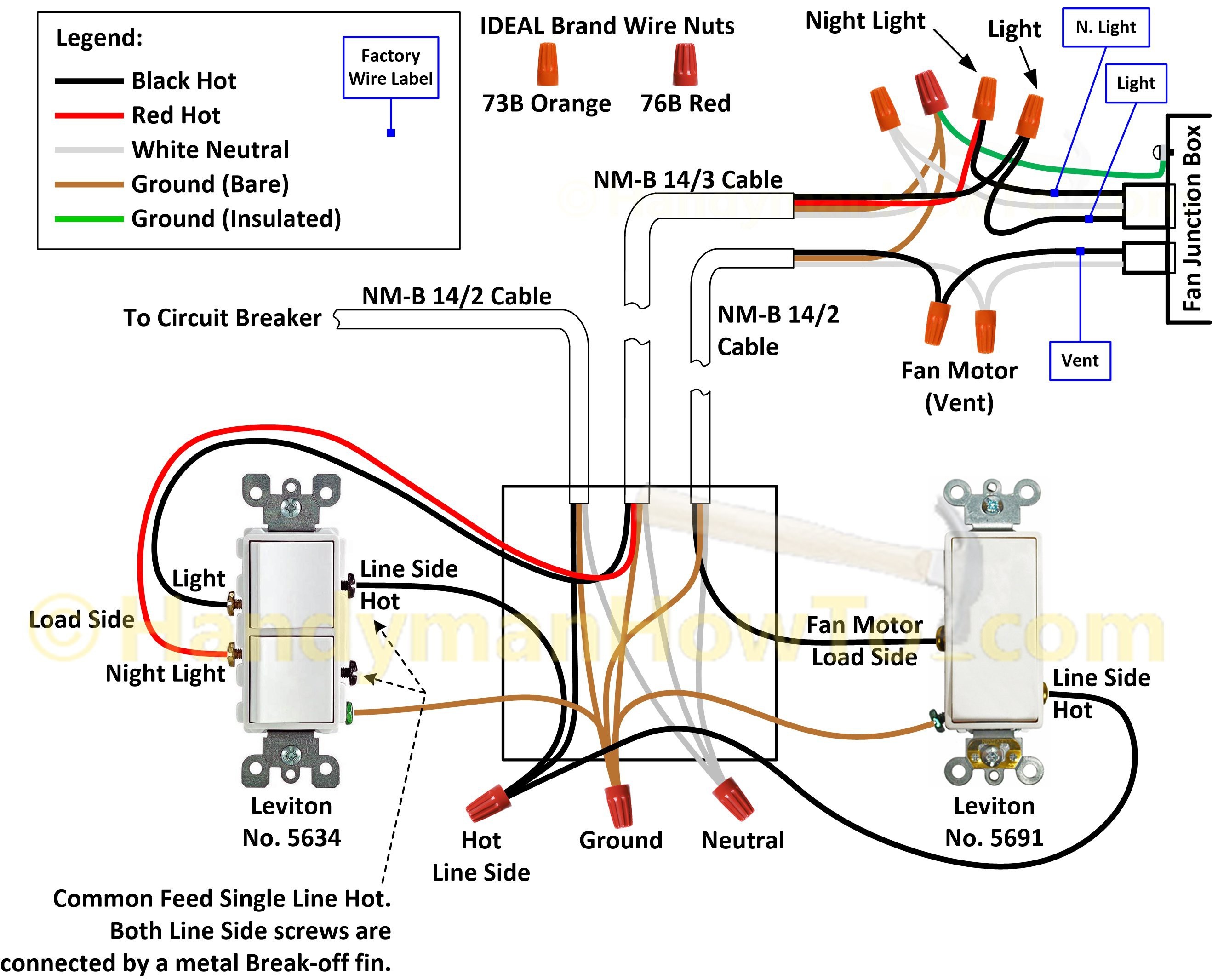
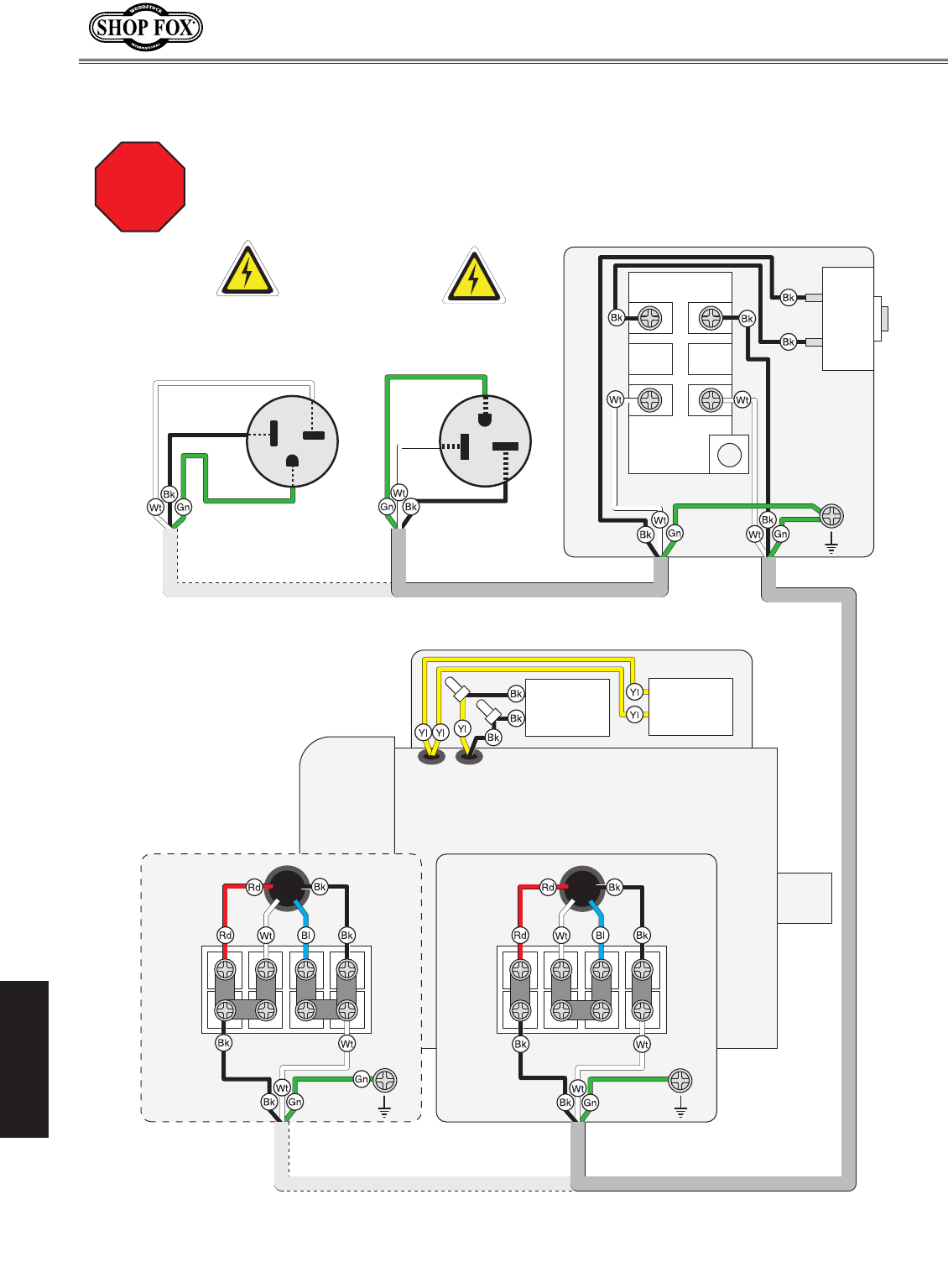
110v 220v motor wiring diagram. What could cause and what should i check for. Fan motor worked for about 12 hour and quit. Adjoining wire paths might be revealed roughly where certain receptacles or fixtures have to be on an usual circuit. I need to see what additional things need be purchased. Most buildings in the united states have electrical service that can supply either 110 or 220 volts v at once and most electric motors are capable of running on either the lower or higher voltage. 220v to 110v wiring diagram wiring diagram is a simplified usual pictorial representation of an electrical circuit.
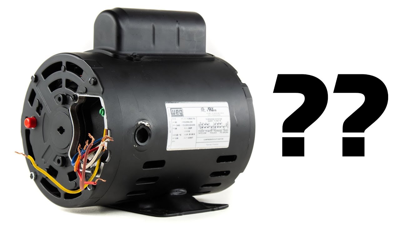
I have the high low connection diagram but the wire coloring does not match possibly somewhat faded but unlikely the diagram and i am nervous about guessing and letting smoke out of the windings. Replaced motor and thermostat. The wiring all looks oem and. Checked wiring diagram and wiring is correct. It shows the components of the circuit as simplified shapes and the capability and signal friends amid the devices. To read a wiring diagram first you need to know exactly what basic components are included in a wiring diagram and also which pictorial icons are used to represent them.
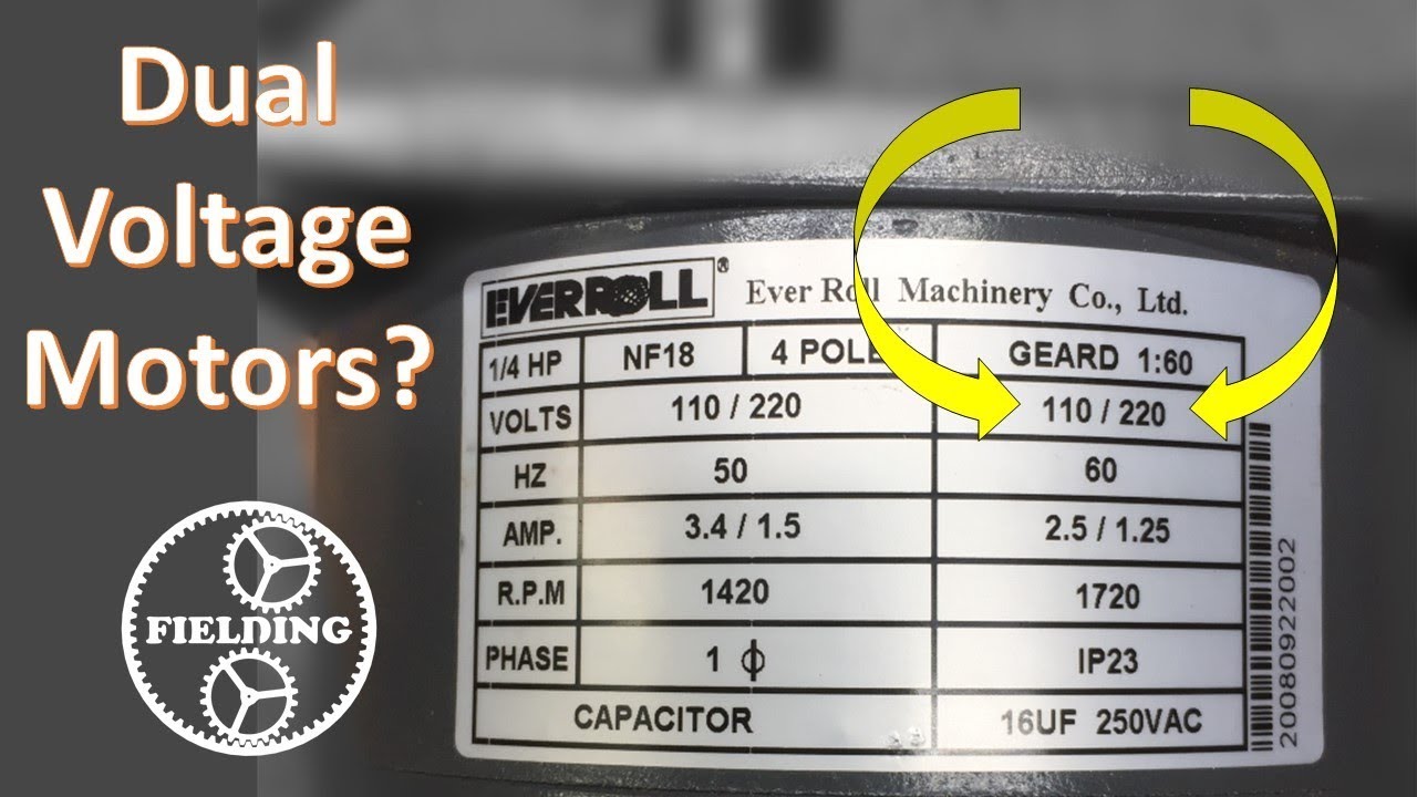
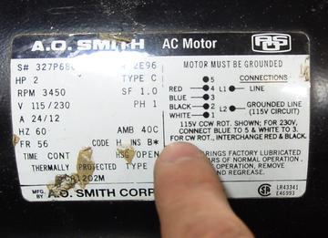
Select a motors 220v or 110v wiring setting by adjusting wires on the terminal plate. My attic 110v vent fan motor stopped working after 23 years. Electric motor wiring diagram 220 to 110 building wiring representations reveal the approximate areas and also interconnections of receptacles illumination and also irreversible electrical solutions in a structure. The wiring diagram will be the same for the 15kw spindle. A list of electric signs and summaries could be found on the electrical icon web page. How to decipher the wiring schematic of a 110220v single phase motor.
Eddie22island electrician replied 6 days ago. By design this setting can be switched. Ill dispense with the background issues unless you really want to hear the story and post my wiring diagram both for checking and for a better way to do it. It shows the components of the circuit as simplified shapes and also the power and signal connections in between the gadgets. A wiring diagram is a simplified conventional photographic representation of an electrical circuit. When you purchase a new appliance or standing tool containing a dual voltage electric motor it comes prewired for either 110 or 220 volt service.
Theres so many switch types and incomplete switch and motor information that its difficult to reach a solid conclusion for a wiring. Answered in 6 minutes by. Can anyone help me decipher how to connect this to high voltage. Select a motors 220v or 110v wiring setting by adjusting wires on the terminal plate. Click the link to respond. By following a wiring diagram you can convert a 220v motor to 110v mode or vice versa fairly easily.
The only difference will depend on if you are using 110v or 220v power as setting pd008 asks you to specify the max voltage. Please send wiring diagram for the 1500kw spindle and inverter combo. The usual aspects in a wiring diagram are ground power supply cord and link outcome devices switches resistors reasoning entrance lights etc. Replaced with new motor and that motor quit after 12 hour. Ask your own electrical question.
Gallery of 110v 220v Motor Wiring Diagram