C4 sw1 z wireless switch 802154 white specifications and supported fixtures this control4 wireless switch operates independently or as part of a control4 home automation system to enable intelligent lighting control. See 5 mount switch into wall box by partially securing the wall box screws attached to the switch.

Control4 Panelized Lighting Wiring
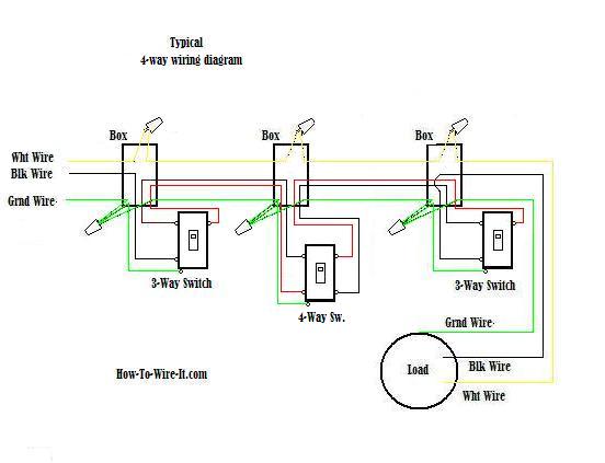
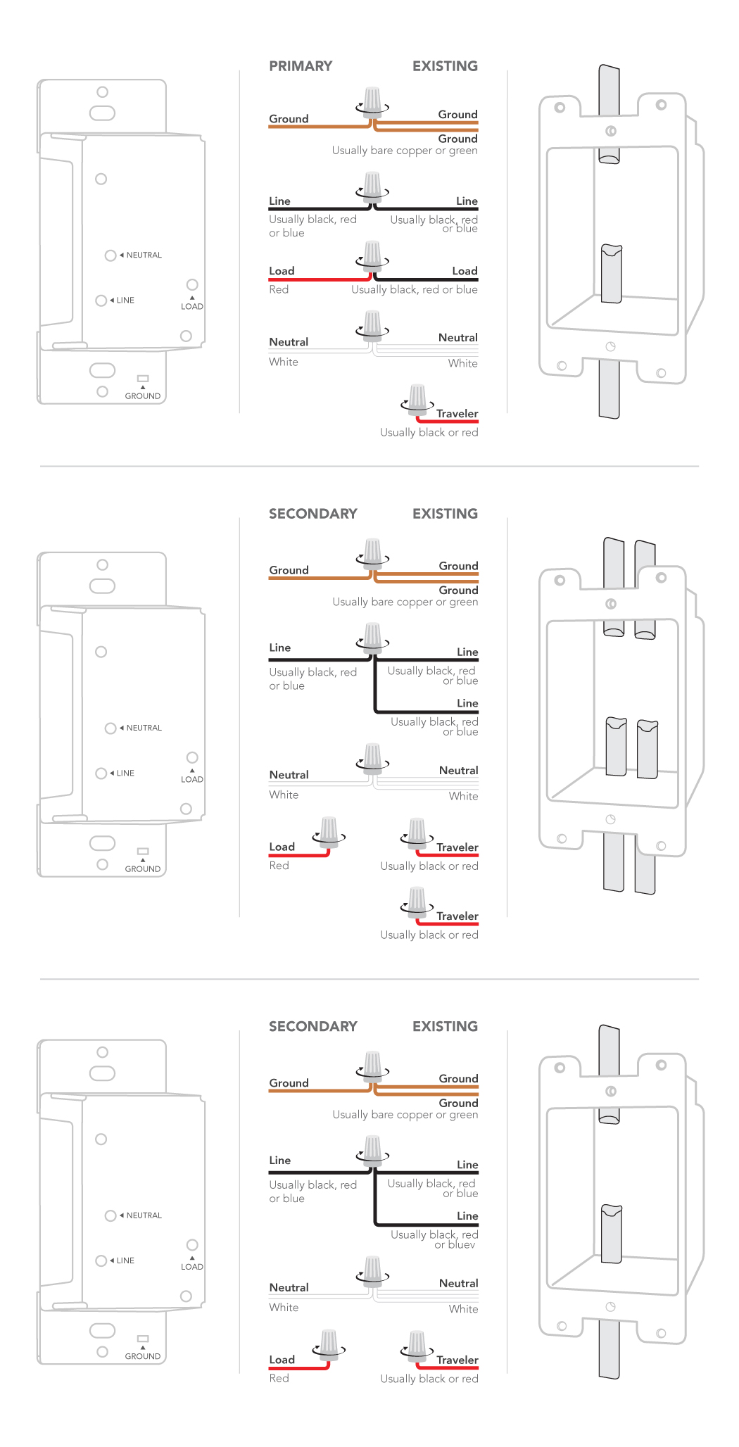
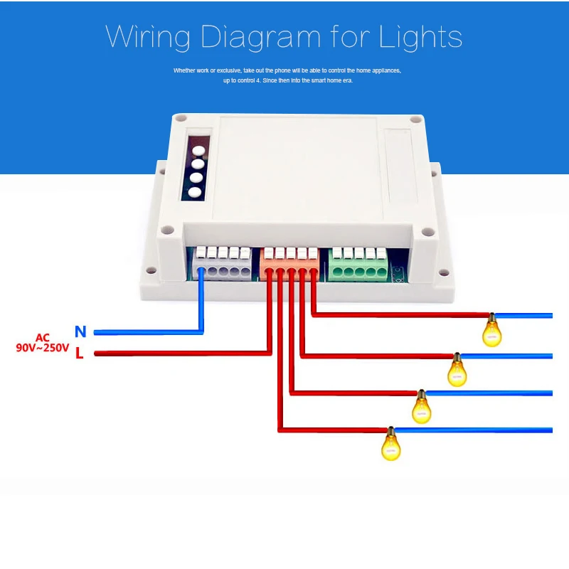
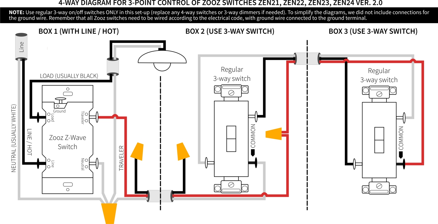
Control 4 switch wiring diagram. Bend the wires in a zigzag. A wiring diagram is a simplified traditional photographic representation of an electric circuit. See sample wiring configurations mount the switch into the wall box by partially securing the wall box screws attached to the switch. The electrical switch box that contains the line and load wires may need to be bigger than the other switch boxes especially if there are other wires going into the switch box. Ensure that the word top on the switch frame is facing up. Thus the blue wire is used to provide power to downstream key pads in 3 way4 way scenarios in order to ensure that all power to the load has been removed when the air gap switch is open.
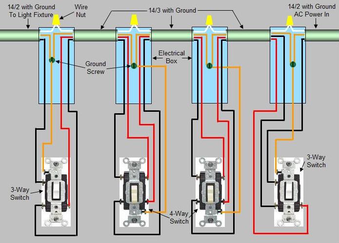
The dimmers hot wire through the air gap switch. Connect the switch wires to the wall box wires using wire nuts according to the relevant wiring diagram. Wiring in control4 panel to ethernet switch distribution breaker. Several diagrams are included here that can be used to map 4 way and 3 way lighting circuits depending on the location of the source in relation to the switches and lights. Actual wire colors differ by country andor voltage. More 4 way switch wiring diagrams four way switch wiring schematic.
Page 3 sample wiring configurations figure 3. It installs in a standard wall box using typical wiring standards and communicates with other devices through a wireless. To set up this switch for use with a control4 system refer to the composer pro user guide. Below is another method for wiring 4 way switches. The wiring diagrams on this page make use of one or more 4 way switches located between two 3 way switches to control lights from three or more points. Power is applied to the blue wire whenever the air gap switch is closed.
Single device location figure 4. Variety of control 4 wiring diagram. Wiring diagrams use these control4 din rail 8 channel relay switch wiring diagrams along with the din rail 8 channel relay switch installation guide ctrl4co8chrelay ig to install din rail 8 channel relay switches. Operation and configuration on initial power up all status leds on the switch will illuminate green indicating that the device has power. Insulation from the appropriate switch leads. Wire insulation should be stripped back 58 of an inch from the wire end as shown.
It shows the components of the circuit as streamlined shapes and the power as well as signal links between the gadgets. 4 connect the switch wires to the wall box wires using wire nuts according to the relevant wiring diagram. Control 4 wiring diagram. See sample wiring.
Gallery of Control 4 Switch Wiring Diagram