See the full list of electrical wiring projects single switch wiring diagram 1. A wiring diagram is a simplified conventional pictorial representation of an electrical circuit.

Residential Electrical Wiring Diagrams Sample Complete Set
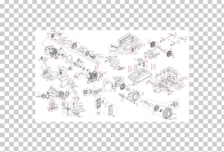
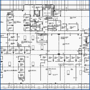
Commercial electrical wiring diagrams. Here is a standard wiring symbol legend showing a detailed documentation of common symbols that are used in wiring diagrams home wiring plans and electrical wiring blueprints. According to power quality primer by barry kennedy the nec is concerned with providing adequate grounding that protects the public from electrical shock. 3 way switch help installing 3 way switch wiring. In addition to wiring diagrams alternator identification information alternator specifications and procedures for the replacement of an older briggs stratton engine with a newer briggs stratton engine that utilizes a different style alternator output connector are also available in this guide. Wiring diagram or pictorial. A simplified conventional pictorial representation of an electrical circuit.
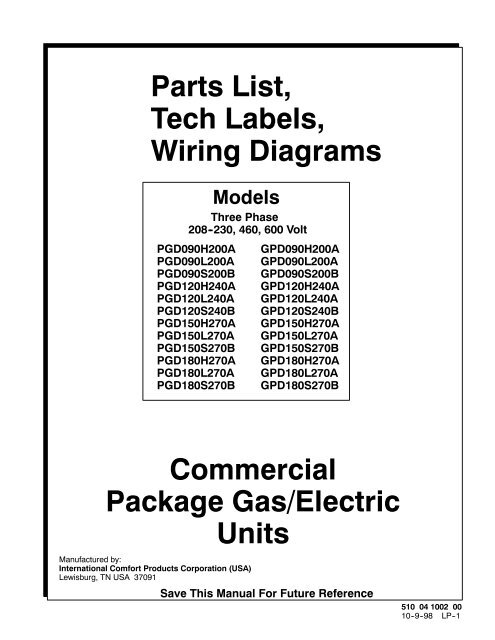
Lets take a look at some key considerations in making sure your commercial electrical wiring is up to the task. From industrial machinery to it infrastructure to advanced security systems to heavy duty hvac equipment and lighting businesses across industries generally require more electricity than residential dwellings. For a more detailed schematic specific to your piece of equipment your best source of information would be the original equipment manufacturer oem. Wiring diagrams use simplified symbols to represent switches lights outlets etc. Wiring layouts are made up of two points. This code states that only licensed electricians can work on commercial electrical wiring and defines proper grounding of electrical wiring and power connections used in commercial buildings.
A wiring diagram is a streamlined traditional pictorial depiction of an electrical circuit. More about wiring diagrams. It shows how the electrical wires are interconnected and can also show where fixtures and components may be connected to the system. It gives detailed information about wiring such that one can get an idea of making connection between the devices. Yes 3 way switches can be installed on a knob and tube wired system as. The electrical wiring diagram is a pictorial representation of the circuit which shows the wiring between the parts or elements or equipments.
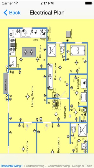
Commercial push button control stations are used to operate gate openers and garage doors from a distance. When and how to use a wiring diagram. Is it possible to install 3 way switches on knob and tube systems. The commercial building telecommunication cabling standard is known as eia 568. Residential electrical wiring diagrams wiring electrical outlets 110 volt outlets 220 volt outlets wiring diagram symbols. A wiring diagram is a simple visual representation of the physical connections and physical layout of an electrical system or circuit.
Single switch wiring diagram 2 related discussion. A wiring diagram is a type of schematic which uses abstract pictorial symbols to reveal all the affiliations of parts in a system. Signs that represent the parts in the circuit and also lines that stand for the links between them. Heavier electrical loads mean commercial properties usually require a larger volume of electrical wire than individual homes. It shows the components of the circuit as simplified shapes and how to make the connections between the devices. This standard is also shared.
Gallery of Commercial Electrical Wiring Diagrams